Expert articles, design standards, and technical guides on VPI, Cast Resin, Power, and Distribution Transformers.
Learn how our type-tested transformers deliver high efficiency and safety across industrial grid networks.
Best practices for selection, installation, and operation of fire-safe, maintenance-free transformers.
Converter Duty Transformer selection starts with the converter, not the nameplate. Rectifiers, inverters, and variable-speed drives impose harmonic currents, voltage distortion, and thermal stress that ordinary load figures may not reveal. The IEA’s Renewables 2024 report forecasts nearly 5,500 GW of renewable power capacity additions worldwide between 2024 and 2030. That growth means more projects will depend on reliable interfaces between power electronics and the grid. A small mismatch can matter.
A sound selection process examines the actual duty cycle, not just rated MVA. Engineers should review harmonic spectra, overload duration, impedance, insulation levels, cooling, tap range, and the converter’s connection arrangement. Site conditions deserve equal attention: altitude, ambient temperature, dust, and available maintenance access can change practical requirements. IEC 60076 provides a relevant framework for power-transformer specifications, but project-specific converter data still matters. Standards are a starting point.
These seven tips focus on decisions that affect service life, efficiency, and commissioning risk. They also encourage careful coordination between the transformer supplier, converter manufacturer, and project engineer. Some specifications are easy to copy from an earlier project. That can be a mistake. Even similar-looking installations may have different harmonic profiles or operating patterns. Use verified operating data where available, document assumptions clearly, and ask for thermal and electrical performance evidence before approving a design.
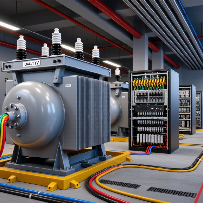
A converter duty transformer sits between the utility supply and power electronics such as rectifiers, inverters, and variable-speed drives. It adapts voltage and may provide electrical isolation or phase shifts for multi-pulse conversion. Its job is not simply to deliver rated kilovolt-amperes. Converter currents contain harmonics, which can increase winding eddy-current losses and hot-spot temperatures. IEEE C57.110-2018 provides guidance for assessing transformer capability under nonsinusoidal currents. The actual harmonic spectrum matters.
Small details count. A six-pulse drive and a high-power electrolytic rectifier can impose very different current patterns. Engineers should review load cycles, harmonic measurements, cooling, impedance, and permitted temperature rise together. A nameplate rating alone can mislead. The IEA’s 2023 report, Electricity Grids and Secure Energy Transitions, estimates that more than 80 million kilometres of grids must be added or refurbished by 2040. That expansion makes dependable conversion equipment increasingly important, but it does not make every site alike. A tidy load sheet may miss future operating changes; revisiting assumptions before specifying the transformer is worthwhile.
Start with the converter’s actual topology, not a catalog rating. A six-pulse bridge and a twelve-pulse arrangement impose different harmonic currents and phase relationships. The transformer may need separate secondary windings, a specified phase shift, or both. Check the converter drawing. Guessing here can create unwanted current paths or undermine intended harmonic cancellation.
Then match electrical duty to the process. Record input voltage, DC output range, current, overload duration, and how often starts occur. A drive feeding a steady pump differs from a furnace rectifier that cycles sharply. Peak current matters. Ask for the converter’s current spectrum and duty cycle; a nameplate kVA alone hides useful detail. Where operating data are incomplete, document assumptions and leave them open to review. A tidy spreadsheet can still miss brief overloads.
Application conditions shape the transformer design. Consider ambient temperature, altitude, enclosure, cooling airflow, and maintenance access. Specify insulation and impedance alongside the system study, since voltage distortion and fault levels interact. Check whether the unit must tolerate regenerative operation or frequent load changes. Small details count. Cable length and poor ventilation can make a sound design run hotter than expected, so compare site measurements with the original assumptions during commissioning.
Tip 1: Start with the converter’s actual input and output requirements, not the nearest standard voltage. Confirm the primary supply, secondary voltage, rectifier arrangement, and allowable voltage variation at the DC terminals. Small mismatches matter. A few volts can affect process stability, especially when the load changes quickly.
Tip 2: Size capacity from the converter’s real operating profile. Use DC output power, efficiency, power factor, and duty cycle to estimate transformer kVA. Then check overloads, ambient temperature, cooling, and harmonic heating. A nameplate load alone can mislead. Ask for measured or specified RMS and peak currents, since rectifier pulses may heat windings more than a smooth-load estimate suggests.
Tip 3: Treat impedance as a design trade-off. Higher impedance can limit fault current, but may increase voltage drop and influence commutation. Lower impedance may improve regulation while raising available fault current. Coordinate the value with protection settings and converter requirements. Verify the waveform. Load data is often incomplete, so revisit the estimate after commissioning measurements.
| Tip | Selection Area | What to Check | Practical Guidance |
|---|---|---|---|
| 1 | Match the primary voltage | Confirm the supply’s nominal voltage, frequency, grounding arrangement, and allowable operating range. | Specify the primary winding for the actual system voltage and frequency. Select tap positions to accommodate the expected supply variation; verify the tap range and operating method with the transformer supplier. |
| 2 | Size secondary voltage for the converter | Identify the rectifier or inverter topology, required DC voltage range, and the converter’s AC-side voltage requirements. | Do not select secondary voltage from the DC voltage alone. The relationship depends on topology, firing angle, commutation overlap, transformer impedance, and operating conditions. Confirm the required secondary voltage with the converter manufacturer’s design data. |
| 3 | Calculate capacity from the duty | Establish the continuous and peak load, duty cycle, power factor, efficiency, overload duration, and ambient conditions. | As an initial estimate for a load specified in real power, apparent power can be approximated by S ≈ P ÷ power factor. For a DC load, include converter and transformer losses when estimating input power. Final kVA selection should use the converter load profile and thermal design, not a generic margin alone. |
| 4 | Account for harmonic heating | Obtain the converter’s harmonic current spectrum, pulse number, operating range, and any filtering or phase-shifting arrangement. | Rectifier currents are non-sinusoidal and can increase winding eddy-current and stray losses. Require a thermal evaluation for the actual harmonic spectrum and specify applicable harmonic-duty design requirements; a standard sinusoidal-load kVA rating may not be sufficient by itself. |
| 5 | Choose impedance for system performance | Review the converter’s permitted transformer impedance, system short-circuit level, voltage regulation, and protection requirements. | Transformer impedance affects fault current and, in converter service, commutation and voltage drop. Higher impedance generally limits short-circuit current but can increase regulation drop and commutation effects. Check the complete operating and fault cases before fixing the percentage impedance. |
| 6 | Specify winding connections and phase shift | Confirm the number of converter bridges, secondary winding connections, phase displacement, and required isolation. | Multi-pulse arrangements may use phase-shifted secondary windings to reduce selected supply-side harmonics. Confirm the vector group and phase displacement against the converter schematic; incorrect phase relationships can prevent the bridges from operating as intended. |
| 7 | Check duty, cooling, and applicable standards | Define overloads, starts, load cycling, cooling method, site altitude, ambient temperature, and installation conditions. | Provide the full duty cycle and environmental data so temperature rise and cooling can be assessed. Ask the project team and manufacturer to confirm the applicable requirements, including IEC 61378-1 for converter transformers where applicable, together with relevant general power-transformer standards and project specifications. |
Design note: These guidelines support preliminary selection only. Final voltage, kVA, impedance, thermal performance, and protection coordination should be verified using the converter manufacturer’s data and a project-specific electrical study.
Tip 1: Measure the harmonic spectrum, not just total harmonic distortion. Record converter operating modes, load levels, and daily duty cycles. A transformer serving a six-pulse rectifier may face different heating patterns from one serving a variable-speed drive. Small details matter. Tip 2: Ask the designer to evaluate harmonic losses and winding hot spots. I would not rely on a single load figure; it can hide uneven operating conditions.
Tip 3: Match the cooling method to actual losses, room temperature, and enclosure airflow. Check whether filters, nearby equipment, or dust could restrict ventilation. Tip 4: Confirm the temperature rise and cooling rating under the expected harmonic load, not only a clean, steady test condition. A warm equipment room changes the margin. It is easy to overlook.
Tip 5: Specify insulation for system voltage and expected electrical stresses. Converter switching can create steep voltage changes, so discuss winding arrangement and insulation coordination with the transformer engineer. Tip 6: Check the insulation temperature class alongside cooling assumptions; one rating alone does not prove a suitable design. Tip 7: Review altitude, moisture, and maintenance access before finalizing the specification. These checks feel mundane, but missing one can complicate installation. Revisit assumptions when the load profile changes.
Assess harmonic loading before selecting transformer capacity, cooling, and insulation.
For an ideal six-pulse rectifier with continuous DC current, characteristic AC line-current harmonics occur at orders 6k ± 1, with approximate magnitudes of 1/h relative to the fundamental. The bars show the 5th, 7th, 11th, and 13th harmonics; actual spectra vary with the converter, system impedance, and operating conditions. Use measured or validated harmonic data to assess additional transformer heating and specify suitable cooling and insulation.
A converter duty transformer faces more than ordinary voltage changes. Rectifier and inverter loads can create harmonics, extra heating, and uneven stress on insulation. Protection should match the converter, transformer design, and fault levels established by an engineering study. Differential protection can detect internal faults, while coordinated overcurrent protection provides backup. Ground-fault protection may also be needed, depending on the system’s grounding arrangement. Settings should be checked against startup currents and the converter’s operating range. A relay that trips too readily can interrupt production; one set too loosely may respond late. Details matter.
Reliability depends on how well the transformer handles heat and operating cycles. Confirm that cooling equipment, temperature alarms, and trip functions suit the expected load. For oil-filled units, inspect for leaks and review oil-test results, including dissolved gas analysis where appropriate. Dry-type units need clean air passages and checks for dust, loose connections, or heat damage. Keep records. A maintenance plan should set inspection intervals from operating conditions, manufacturer guidance, and past findings—not a calendar alone. Infrared scans can reveal hot connections, but they cannot explain every cause. I have seen maintenance plans look complete on paper, yet miss small changes between inspections. Reviewing trends and revising the plan can help catch those changes earlier.
A six-pulse bridge and a twelve-pulse arrangement produce different harmonic currents and phase relationships. Check the converter drawing before specifying secondary windings or phase shifts. Guessing can create unwanted current paths.
Record input voltage, DC output range, current, overload duration, and start frequency. Ask for the converter’s current spectrum and duty cycle. Peak current matters.
No. A single kVA figure can hide short overloads and uneven operating conditions. Compare it with real process data, such as a pump’s steady load or a furnace’s sharp cycles.
Measure the harmonic spectrum at different load levels and operating modes. Have the designer assess harmonic losses and winding hot spots. Total distortion alone may miss important heating patterns.
Check room temperature, enclosure airflow, filters, dust, and nearby equipment. Restricted ventilation can raise operating temperatures. Small details count.
Specify insulation for the system voltage and expected electrical stresses. Discuss switching-related voltage changes, winding arrangement, and insulation coordination with the transformer engineer. One rating is not enough.
Review altitude, moisture, ambient temperature, cable length, and maintenance access. Poor ventilation or long cable runs may affect operating temperatures. I may still be overlooking something.
Review them during commissioning and whenever the load profile changes. Compare site measurements with the assumptions used in the design. A tidy spreadsheet can still miss brief overloads.
Choosing the right Converter Duty Transformer begins with understanding how it connects to the converter and supports the demands of the application. Consider the converter type, operating conditions, and load behavior before selecting a transformer. Voltage, capacity, and impedance should be matched carefully to the system so the transformer can handle expected power requirements while supporting stable operation.
Also assess harmonic loads, since they can affect heating and performance. Select suitable cooling and insulation for the environment and duty cycle, then compare protection features, reliability, and maintenance needs. A thoughtful evaluation of these factors helps ensure the transformer is appropriately sized, resilient under operating conditions, and practical to maintain throughout its service life.