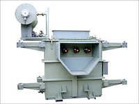
1. Technical Fundamentals of Heavy Duty Converter Duty Transformers
In modern industrial power distribution, the rapid adoption of non-linear electrical loads—such as variable frequency drives (VFDs), high-power thyristor rectifiers, electric arc furnaces, solar photovoltaic (PV) central inverters, and battery energy storage systems (BESS)—has fundamentally altered the electromagnetic demands placed on step-up and step-down transformers. Standard distribution and power transformers are designed primarily for pure sinusoidal 50/60 Hz utility power. When subjected to the severe harmonic currents, high dV/dt voltage spikes, and DC bias produced by modern solid-state power electronics, conventional transformers suffer from rapid thermal degradation, premature insulation failure, excessive core saturation, and catastrophic mechanical coil deformation.
A Heavy Duty Converter Duty Transformer is a specialized electromagnetic power apparatus purpose-built to withstand the severe electrical, thermal, and mechanical stresses unique to static power converter circuits. Unlike standard grid transformers, converter duty transformers incorporate multi-phase phase-shifting secondary windings, reinforced electrostatic inter-winding shielding, custom K-factor thermal design algorithms, and high-frequency lamination core geometries to handle non-sinusoidal current waveforms without exceeding allowable IEEE/IEC temperature rise thresholds.
Why Standard Transformers Fail in Converter Applications
When solid-state semiconductor switches (IGBTs, Thyristors, SCRs) chop AC power into DC or invert DC to AC, they generate substantial harmonic frequencies ($h = 5, 7, 11, 13, 17, 19, \dots$). These harmonic currents create severe operational challenges within standard transformer windings:
- Harmonic Eddy Current Losses ($P_{EC}$): Eddy current losses in transformer windings increase proportional to the square of the harmonic frequency ($f^2$). In standard transformers, 11th and 13th harmonics cause intense localized hot-spots, accelerating insulation thermal aging according to Arrhenius's law.
- Stray Load Losses in Structural Clamping ($P_{OS}$): High-frequency harmonic leakage flux penetrates structural steel core clamps, tie-bars, and tank walls, causing severe local overheating and degradation of transformer cooling oil or dry insulation.
- Extreme dV/dt Transient Stress: High-switching-frequency VFDs (using pulse-width modulation - PWM) subject the first few turns of the primary winding to steep voltage wavefronts (high $dV/dt$), causing dielectric breakdown across turn-to-turn insulation.
- DC Bias & Core Saturation: Asymmetrical firing angles in power rectifiers induce a direct current (DC) component into the transformer secondary. This DC bias shifts the core magnetic operating point toward saturation, exponentially increasing no-load losses, excitation currents, and acoustic noise emissions.
- Severe Dynamic Short-Circuit Forces: In heavy industrial applications like steel rolling mills or chemical electrolysis, rapid cyclic load switching produces severe electromagnetic forces on winding conductors, requiring extraordinary mechanical anchoring and structural clamping rigidity.
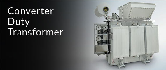
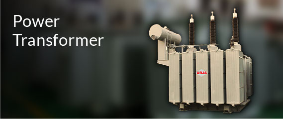
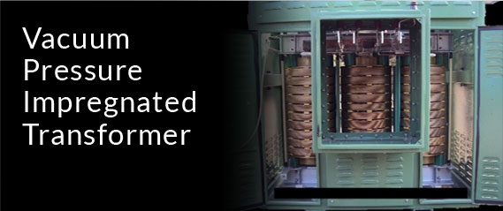
Figure 1.1: Precision-engineered core and coil assembly of a Heavy Duty Converter Duty Transformer at Urja Techniques manufacturing plant.