1. Executive Summary & Information Gain: Why Standard Power Transformers Fail Under Converter Loads
In modern industrial energy ecosystems, solid-state power conversion systems—such as Variable Frequency Drives (VFDs), thyristor-based rectifiers, green hydrogen electrolyzers, solar photovoltaic inverters, and traction sub-stations—are essential. However, supplying power to non-linear semiconductor switches (IGBTs, Thyristors, and Diodes) introduces non-sinusoidal current waveforms rich in high-frequency harmonics (5th, 7th, 11th, 13th, 17th, 19th, 23rd, 25th, and higher order harmonics).
When conventional distribution or standard power transformers are subjected to these non-linear converter loads, they suffer catastrophic premature degradation. Standard power transformers are rated solely for sinusoidal 50 Hz or 60 Hz fundamental frequencies. Non-sinusoidal harmonic currents induce severe secondary electromagnetic phenomena:
- Exponential Eddy Current Loss Escalation: Winding eddy current losses increase proportionally to the square of the harmonic frequency ($P_{ec} \propto f^2$). High-frequency harmonics turn transformer windings into intense heat generators.
- Stray Stray Field Heating: High-frequency leakage flux penetrates structural steel clamping frames, core tie bars, and tank walls, causing localized thermal hot spots that degrade mineral insulation oil and cellulose paper.
- DC Magnetization & Asymmetric Saturation: Unsymmetrical firing angles in semiconductor rectifiers superimpose DC bias components on transformer windings, pushing the magnetic core into saturation and generating high magnetizing inrush currents.
- Dielectric Voltage Stress: Rapid solid-state switching rates ($dv/dt$) generate high-voltage stress transients and reflected voltage pulses across the initial turns of transformer windings, eroding turn-to-turn insulation.
A Converter Duty Transformer is specifically engineered, thermally derated, and structurally reinforced to withstand non-sinusoidal current harmonics, severe thermal hot spots, mechanical short-circuit forces, and high $dv/dt$ voltage transients. Engineering a converter duty transformer requires precise electromagnetic modeling, customized phase-displacement vector topologies, electrostatic shielding, and specialized cooling channel geometries.
Key Technical Takeaway for Procurement Managers
Installing a standard power transformer on a 12-pulse or 24-pulse converter drive system results in up to 40% thermal capacity reduction, elevated noise levels (>85 dBA), insulation thermal breakdown within 36 to 48 months, and catastrophic field failure. A purpose-built Converter Duty Transformer from Urja Techniques guarantees full nameplate kVA rating utilization, IEEE C57.110 K-factor compliance, and a 30+ year operational design life under severe non-linear harmonic loading.
2. Electromagnetic Architecture & Multi-Pulse Phase Shifting Topology
To reduce Total Harmonic Distortion (THD) injected back into the primary utility grid, industrial drive systems employ multi-pulse rectifier arrangements (6-pulse, 12-pulse, 18-pulse, 24-pulse, or 48-pulse). The Converter Duty Transformer acts as both an isolation medium and a precise harmonic cancellation network through spatial phase displacement between secondary windings.
Phase Displacement Formula
The required phase shift ($\alpha$) between adjacent secondary windings in an $N$-pulse converter system is determined by the fundamental phase-cancellation equation:
\alpha = \frac{60^\circ}{k} \quad \text{or} \quad \alpha = \frac{30^\circ}{\text{Number of 6-pulse bridges}}
For a 12-pulse converter system (comprising two 6-pulse rectifier bridges), a 30° phase shift is required between secondary outputs. This is achieved by combining a Star (Y) connected secondary with a Delta ($\Delta$) connected secondary on the same magnetic core limb.
Harmonic Elimination Spectrum
By phase-shifting secondary outputs by $30^\circ$, low-order line current harmonics generated by the individual 6-pulse bridges cancel out on the primary supply side. The low-order harmonics eliminated are defined by:
h = k \cdot p \pm 1
Where $p$ is the pulse number and $k = 1, 2, 3...$. Consequently, in a 12-pulse transformer system, the 5th and 7th harmonics are completely eliminated from the primary utility side, leaving only the 11th, 13th, 23rd, and 25th harmonics.
For high-power variable speed drives (VFDs) and heavy electrochemical facilities, 18-pulse ($20^\circ$ phase shift) and 24-pulse ($15^\circ$ phase shift) configurations are deployed. Urja Techniques engineers multi-winding converter transformers featuring extended delta, zigzag, or quad-secondary physical arrangements, maintaining tight impedance symmetry (less than 1.5% impedance variance across secondary windings) to ensure equal current sharing across parallel rectifier bridges.
3. Recommended Converter Duty Transformer Portfolio by Urja Techniques
Urja Techniques (India) Pvt. Ltd. manufactures a broad portfolio of custom-designed Converter Duty Transformers engineered for indoor, outdoor, hazardous, and extreme climatic operating environments. Below are our core product series recommended for global B2B industrial procurement:
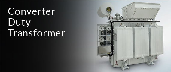
12-Pulse & 24-Pulse Oil-Immersed Converter Duty Transformer
Designed for heavy industrial drives, steel rolling mills, and mining winches. Utilizes ONAN/ONAF cooling, high-grade CRGO laminations, thermally upgraded paper insulation, and electrostatic copper shields between primary and secondary windings.
- Capacity Range: 500 kVA to 25 MVA
- Voltage Class: Up to 33 kV
- Pulse Configurations: 6-Pulse, 12-Pulse, 18-Pulse, 24-Pulse
- Standards: IEC 60076-6, IS 2026, IEEE C57.18.10
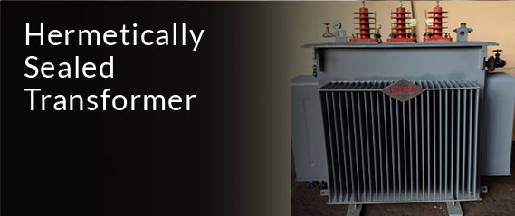
VPI (Vacuum Pressure Impregnated) Dry-Type Converter Transformer
Engineered for fire-sensitive environments including high-rise commercial structures, data centers, underground mines, and metro rail sub-stations. Impregnated with high-temperature Class H (180°C) resin under deep vacuum.
- Capacity Range: 250 kVA to 10 MVA
- Insulation Class: Class H (180°C) or Class C (220°C)
- Feature: Moisture-proof, self-extinguishing, low maintenance
- Application: Indoor VFD drives & cleanroom environments
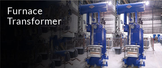
Cast Resin Dry-Type (CRT) Converter Duty Transformer
Encapsulated in epoxy resin under vacuum, offering complete protection against moisture, dust, chemical vapors, and high salt humidity. Ideal for marine platforms, chemical processing, and offshore wind substations.
- Capacity Range: 315 kVA to 12.5 MVA
- Protection Rating: IP23 to IP54 enclosures available
- Environmental Class: E2, C2, F1 certified
- Feature: Maintenance-free with exceptional impulse withstand
Heavy Industrial Rectifier & Electrochemical Duty Transformer
Tailored for extra-high DC current applications such as chlor-alkali electrolysis, aluminum smelting, copper electrowinning, and green hydrogen electrolyzer plants requiring continuous heavy-duty DC supply.
- Secondary Current Output: Up to 100,000 Amperes DC
- Integrated Saturable Reactors & On-Load Tap Changers
- Cooling Mediums: ODAF, OFWF, or Hydro-air heat exchangers
- Feature: Robust mechanical design for magnetic short-circuit forces
Technical Specification Matrix: Converter Duty vs. Standard Power Transformer
| Engineering Parameter | Standard Power Transformer | Urja Converter Duty Transformer | Engineering Benefit |
|---|---|---|---|
| Harmonic Capability | Fundamental 50/60 Hz only (K-1 rating) | Custom K-Factor rated (K-4, K-13, K-20, K-30) | Prevents thermal overheating under harmonic distortion |
| Winding Conductor Design | Standard rectangular copper/aluminum wire | Continuously Transposed Conductors (CTC) or Foil Winding | Dramatically reduces eddy current losses at high harmonic frequencies |
| Phase Displacement | Single vector (e.g., Dyn11 or Ynd11) | Multi-vector phase shifts (Dyn11Y0, Ddy, Ddz) for 12/24-pulse | Eliminates 5th, 7th, 17th, and 19th grid harmonics |
| Electrostatic Shielding | Rarely installed | Grounded copper electrostatic shield between windings | Attenuates high-frequency common-mode noise and switching transients |
| Mechanical Short-Circuit Strength | Designed for standard grid fault currents | Reinforced clamping structure, pre-stressed coil bracing | Withstands frequent rectifier short-circuit commutation surges |
| Thermal Hot Spot Design | Standard top oil rise gradient (60°C/65°C) | Reduced flux density (1.55 to 1.6 Tesla) & enhanced oil ducts | Prevents localized insulation degradation and thermal runaway |
4. Future Procurement Trends & Technology Evolution in Converter Transformers
As global energy transitions accelerate, procurement requirements for Converter Duty Transformers are evolving rapidly. Technical buyers and EPC decision-makers must consider several high-impact technology shifts when finalizing equipment specifications for upcoming projects:
Trend 1: Green Hydrogen & GW-Scale Water Electrolysis Power Supplies
The rapid expansion of Green Hydrogen production facilities requires massive Direct Current (DC) inputs for Proton Exchange Membrane (PEM) and Alkaline electrolyzers. Electrolyzer power supply systems mandate massive multi-pulse rectifier transformers capable of operating continuously at full load while subjected to ripple currents. Urja Techniques is actively engineering dual-input multi-secondary converter transformers rated for 33 kV grid integration to power 10 MW to 100 MW electrolyzer modules.
Trend 2: Medium Voltage VFD Drives in Mining & Heavy Industry
Heavy industries (cement kilns, underground mining hoists, steel rolling mills) are transitioning from low-voltage drives to Medium-Voltage (MV) Variable Frequency Drives (3.3 kV, 6.6 kV, and 11 kV). This transition demands multi-winding dry-type and oil-immersed converter transformers with up to 4 or 6 separate secondary windings on a single core limb, requiring precise balance in leakage reactance across all windings.
Trend 3: Environmentally Friendly & High-Fire-Point Ester Dielectric Liquids
Traditional mineral transformer oil is increasingly being replaced by biodegradable Synthetic Esters and Natural Organic Esters. Ester fluids possess a fire point exceeding 300°C (K-class fluid), making them self-extinguishing while offering superior moisture absorption capacity. For offshore platform converter transformers and indoor industrial plants, Urja Techniques offers ester-filled converter duty transformers that comply with stringent environmental and fire safety directives.
Trend 4: Smart Condition Monitoring & AI-Driven Predictive Maintenance
Modern procurement guidelines increasingly mandate smart digital integration. Urja Techniques fits converter duty transformers with fiber-optic hot-spot sensors directly embedded within critical winding turns, online Dissolved Gas Analysis (DGA) monitors, micro-processor magnetic flux sensors, and IoT-enabled gateway modules. This enables AI algorithms to monitor thermal aging and predict insulation degradation in real time.
5. Enterprise Advantages & E-E-A-T Capabilities of Urja Techniques (India) Pvt. Ltd.
When selecting a global partner for specialized electrical equipment, technical competence, manufacturing infrastructure, and quality assurance records are paramount. Urja Techniques (India) Pvt. Ltd. stands as a trusted leader in transformer manufacturing, built on over three decades of engineering excellence.
30+ Years of Manufacturing Mastery (Since 1991)
Established in 1991 in Mumbai, Maharashtra, Urja Techniques has consistently engineered custom power solutions for utility grids, Fortune 500 multinationals, state electricity boards, and turnkey EPC contractors globally.
Rigorous Global Quality Certifications
Our state-of-the-art manufacturing facility operates under strict Quality Management Systems certified to ISO 9001:2015, ISO 14001:2015, and ISO 45001:2018. All designs comply with IEC 60076, IS 2026, IS 1180, and IEEE C57 standards.
ERDA & CPRI Accredited Type-Test Validation
Our transformers have undergone rigorous independent type-testing at premier NABL-accredited test laboratories—including CPRI (Central Power Research Institute) and ERDA (Electrical Research and Development Association)—for short-circuit withstand, impulse voltage withstand, acoustic noise, and temperature rise.
Global Footprint: Exporting to 40+ Countries
Over 40% of our total revenue is derived from international exports across Africa, the Middle East, Europe, South America, and Southeast Asia, demonstrating our ability to meet varied international grid codes and severe climatic demands.
Urja Techniques operates an in-house, BIS-recognized Temperature Rise Testing Facility and advanced impulse voltage test labs, ensuring that every Converter Duty Transformer manufactured undergoes 100% routine testing—including dissolved gas analysis, partial discharge measurement, winding resistance, vector group verification, and zero-sequence impedance measurement—prior to dispatch.
6. Comprehensive B2B Buyer FAQ: Answering Global Procurement Queries
Global procurement teams and electrical engineering consultants frequently ask critical technical questions when evaluating Converter Duty Transformers. Below, our senior engineering team addresses these key user intent queries in depth:
The K-Factor is a weighted value calculating a transformer's capability to handle non-linear harmonic currents without exceeding rated temperature limits. It is calculated using the formula specified in IEEE C57.110:
K = \sum_{h=1}^{h_{max}} I_h^2 \cdot h^2
Where $I_h$ is the per-unit rms current at harmonic order $h$. For standard 6-pulse VFD drives, a K-4 or K-9 rating is typical. For 12-pulse rectifiers, K-13 is standard. For intense thyristor rectifiers in electrolysis or DC furnace duty, K-20 to K-30 ratings are mandatory. Urja Techniques conducts complete harmonic spectrum analysis to select the exact conductor cross-section and core flux density for your specified K-Factor.
An electrostatic shield is a grounded sheet of high-purity copper or aluminum positioned between the primary (grid-side) and secondary (converter-side) windings. Solid-state switching devices (IGBTs/Thyristors) create rapid voltage transients ($dv/dt$) and high-frequency common-mode noise. The electrostatic shield acts as a low-impedance capacitive bypass route, diverting high-frequency electric field noise directly to earth ground and preventing it from coupling back into the high-voltage utility power line.
To eliminate localized winding hot spots, Urja Techniques employs several advanced thermal and structural design strategies:
- Continuously Transposed Conductors (CTC): Using multiple individually insulated copper strands transposed along the length of the winding to minimize eddy current loss gradients.
- Reduced Working Magnetic Flux Density: Designing the core to operate at lower flux density levels (typically 1.50 Tesla to 1.58 Tesla instead of 1.70 Tesla) to prevent core saturation from DC components.
- Directed Oil Flow & Cooling Channels: Incorporating additional vertical and radial oil cooling ducts between winding layers to lower the hot-spot temperature rise to within IEEE/IEC guidelines.
For a 12-pulse converter system powered by a single transformer tank housing two secondary windings, the standard recommended vector group is Dyn11Y0 or Ynd11d0. In this configuration, Secondary Winding 1 is Delta-connected ($\Delta$) with a 30° phase lag, while Secondary Winding 2 is Star-connected ($Y$) with a 0° phase shift. This 30° phase displacement between secondary outputs cancels the 5th and 7th harmonic currents on the primary side.
Yes. Cast Resin Dry-Type (CRT) Converter Duty Transformers housed in heavy-duty IP54 or IP55 weatherproof enclosures with air-to-air heat exchangers (NEMA 3R or NEMA 4X rated) are highly effective for outdoor industrial environments. They eliminate oil leakage risks, are non-flammable, and resist corrosive chemical atmospheres.
Every converter transformer manufactured by Urja Techniques undergoes rigorous FAT procedures prior to shipment, including:
- Measurement of winding resistance and voltage turns ratio at all tap positions.
- Vector group check and phase displacement angle verification ($30^\circ \pm 0.5^\circ$).
- Measurement of short-circuit impedance and load losses across all secondary pairs.
- Separate-source AC withstand voltage test and induced overvoltage test.
- Partial Discharge (PD) measurement (for dry-type units: < 10 pC).
- Insulation resistance measurement and Dissolved Gas Analysis (DGA) baseline testing.
To receive an accurate customized technical bid from Urja Techniques, please provide:
- Rated kVA / MVA capacity and primary supply voltage (e.g., 11 kV, 22 kV, 33 kV).
- Number of converter pulses (6-pulse, 12-pulse, 18-pulse, or 24-pulse).
- Rectifier type (Thyristor bridge, Diode bridge, or IGBT inverter).
- DC output voltage and maximum continuous DC current rating.
- Specified K-factor rating or detailed current harmonic spectrum.
- Site environmental conditions (ambient temperature, altitude, indoor/outdoor, installation area constraints).