
1. What is an Industrial Rectifier Transformer? Operational Architecture & Information Gain
An Industrial Rectifier Transformer is a highly specialized transformer engineered specifically to supply power to solid-state rectifiers (such as diode or thyristor bridges). Unlike conventional AC distribution or power transformers operating under clean sinusoidal 50/60 Hz conditions, an industrial rectifier transformer operates under continuous non-sinusoidal current waveforms characterized by steep current transitions, severe harmonic distortion, and significant DC offset loads.
The primary engineering objective of an industrial rectifier transformer is to step down medium or high utility transmission voltages (e.g., 11kV, 22kV, 33kV, or 132kV) to precise, low secondary AC voltages while providing multi-phase outputs (such as 6-pulse, 12-pulse, 24-pulse, or 48-pulse phase shifts). These secondary AC outputs feed high-power rectifier stacks to produce controlled, high-amperage direct current (DC) required for intensive industrial processes including aluminium smelting, chlor-alkali electrolysis, arc furnace operation, and modern green hydrogen electrolyzers.
Key Engineering Information Gain: Rectifier Duty vs. Standard Power Transformers
Standard AC transformers rated according to IEC 60076-1 will rapidly overheat and experience premature insulation degradation if connected directly to non-linear rectifier loads. Rectifier transformers must incorporate deliberate structural and electromagnetic compensations:
- Enhanced Stray Load Loss Compensation: Eddy current losses in the windings scale with the square of the harmonic frequency ($P_{eddy} \propto \sum I_h^2 \cdot h^2$). Windings must utilize fine stranded Continuously Transposed Conductors (CTC) or thin copper foil to minimize skin and proximity effects.
- Mechanical Short-Circuit Bracing: Rectifier circuits experience sudden load fluctuations, frequent commutation short-circuits, and severe thermal shocks. The internal clamping structure must withstand radial and axial forces up to 25 times nominal stress.
- DC Magnetization & Flux Shielding: Unsymmetrical thyristor firing can introduce a continuous DC bias current into the transformer secondary windings. Magnetic cores must be designed with reduced flux density ($B_{max} \le 1.55 \text{ Tesla}$) to prevent core saturation and localized tank heating.
| Technical Parameter | Standard Power Transformer | Industrial Rectifier Transformer |
|---|---|---|
| Operating Waveform | Sinusoidal 50 Hz / 60 Hz AC | Non-Sinusoidal with severe harmonic currents ($h = 5, 7, 11, 13, 17, 19...$) |
| Primary Winding Configuration | Delta ($\Delta$) or Star ($Y$) | Delta ($\Delta$), Star ($Y$), or Extended Delta with specific phase displacement angles |
| Secondary Winding Design | Single 3-Phase Secondary Output | Multiple isolated secondary windings ($\Delta, Y, Z$) for multi-pulse operation |
| Thermal Design Standard | IEC 60076-2 standard ambient limits | IEC 60076-8 & IEEE C57.18.10 with K-Factor & harmonic loss weighting |
| Winding Conductor Type | Standard rectangular copper/aluminium wires | Continuously Transposed Conductors (CTC) or transposed foil windings |
| Cooling Medium Options | ONAN, ONAF | ONAN, ONAF, OFWF (Oil Forced Water Forced), or VPI Dry-Type |
2. Recommended Industrial Rectifier Transformer Solutions
Urja Techniques (India) Pvt. Ltd. manufactures a wide array of heavy-duty Industrial Rectifier Transformers engineered for extreme operating environments. Below are our core recommended configurations trusted by global EPC contractors and industrial operators.
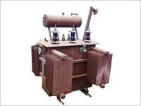
Electrochemical Process Rectifier Transformer
Specifically custom-engineered for chlor-alkali plants, copper/zinc electro-refining, and continuous chemical electrolysis requiring steady low-voltage, high-DC current outputs.
- • Capacity: Up to 30 MVA / 100 kA DC
- • Configuration: 12-Pulse / 24-Pulse
- • Standard: IEC 60076-6 / IS 2026
- • Cooling: OFWF / ONAF / ONAN
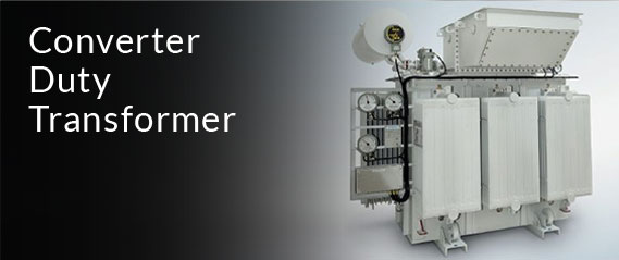
Green Hydrogen & VFD Converter Duty Transformer
Designed for medium-voltage industrial Variable Frequency Drives (VFD) and megawatt-scale PEM/Alkaline green hydrogen water electrolyzers requiring precise voltage regulation.
- • Capacity: 1 MVA to 25 MVA
- • Pulse Rating: 18-Pulse, 24-Pulse, 48-Pulse
- • Harmonic Mitigation: IEEE 519 Compliant
- • Winding: Continuously Transposed Copper
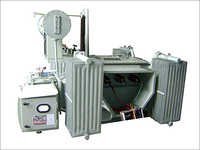
Heavy-Duty Arc & Smelting Rectifier Transformer
Ruggedized for steelworks, graphite heating, and submerged arc furnace rectifier circuits exposed to violent load swings, transient overvoltages, and high thermal strain.
- • Capacity: Up to 45 MVA
- • Tap Changer: On-Load Tap Changer (OLTC)
- • Bracing: Enhanced Mechanical Short-Circuit
- • Testing: CPRI / ERDA Type Tested
3. Future Procurement Trends in Industrial Rectifier Transformers (2025–2035)
Global industrial procurement strategies for high-power electrical apparatus are undergoing a massive transformation driven by grid decarbonization, stringent harmonic control regulations, and energy efficiency mandates. Procurement directors and engineering consultants must account for the following five key macro trends when specifying rectifier transformers over the next decade:
Trend 1: Rapid Scale-Up of Green Hydrogen Electrolyzer Infrastructure
The global push toward net-zero emissions has positioned green hydrogen as a key industrial energy vector. Water electrolysis plants (both Proton Exchange Membrane [PEM] and Alkaline Electrolysis [AEL]) require dedicated mega-watt scale rectifiers. Procurement demands are shifting toward multi-pulse (24-pulse and 48-pulse) rectifier transformers with step-less On-Load Tap Changers (OLTC) and integrated saturated reactors to deliver high DC current with minimal voltage ripple (<2%), maximizing electrolyzer stack lifetime and system conversion efficiency.
Trend 2: Strict Total Cost of Ownership (TCO) & Loss Capitalization Procurement Models
Modern procurement tenders no longer evaluate vendors solely on initial capital expenditure (CAPEX). Leading EPCs utilize stringent Loss Capitalization formulas to assess Total Cost of Ownership (TCO):
TCO Capitalization Formula
$$\text{TCO} = \text{CAPEX} + (A \times P_{no\text{-}load}) + (B \times P_{load\text{-}harmonic})$$
Where $A$ represents the capitalized cost per kilowatt of no-load (core) loss ($\$4,000 - \$8,000/\text{kW}$) and $B$ represents the capitalized cost of load losses including harmonic eddy components ($\$2,000 - \$4,500/\text{kW}$). Urja Techniques utilizes high-grade, laser-scribed Cold Rolled Grain Oriented (CRGO) steel cores and optimized copper winding structures to minimize overall loss profiles, offering buyers significant lifetime operational savings.
Trend 3: Transition to Biodegradable Synthetic and Natural Ester Liquids
Environmental containment mandates and indoor fire-safety codes are accelerating the replacement of traditional mineral oil with natural or synthetic ester transformer fluids (K-class fluids). Ester fluids feature fire points exceeding $300^\circ\text{C}$, high moisture tolerance, and 100% biodegradability within 28 days, making them essential for offshore chemical platforms, urban electrolysis hubs, and underground mining operations.
4. Technology Development & Advanced Engineering Trends
To overcome severe harmonic heating and electromagnetic mechanical stress, next-generation industrial rectifier transformer engineering incorporates several breakthrough methodologies:
A. Finite Element Method (FEM) 3D Electromagnetic & Thermal Modeling
Traditional empirical calculations fail to capture localized hot-spot temperatures caused by eddy currents near winding edges and internal clamping structure elements. Modern design employs full 3D Finite Element Analysis (FEA) to simulate stray magnetic leakage fields. This allows engineers to place localized magnetic shielding (silicon steel shunts or aluminum shields) along internal tank walls, reducing stray tank losses by up to 60% and preventing insulation scorching.
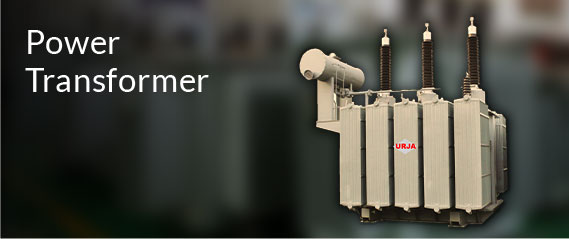
B. Advanced Phase Shift Windings for Superior Harmonic Cancellation
Higher-order current harmonics cause severe grid voltage distortion, high neutral currents, and potential resonance with power factor correction capacitors. By employing primary extended-delta or zigzag phase-shifting windings combined with dual secondary delta-star ($\Delta / Y$) outputs, transformers achieve internal phase offsets of $15^\circ$ (for 12-pulse), $7.5^\circ$ (for 24-pulse), or $3.75^\circ$ (for 48-pulse).
This physical phase cancellation eliminates low-order harmonics ($5^{\text{th}}, 7^{\text{th}}, 11^{\text{th}}, 13^{\text{th}}$) on the high-voltage utility grid side without requiring massive external passive filter banks, allowing full compliance with IEEE 519-2022 harmonic limits at the Point of Common Coupling (PCC).
5. Global Procurement FAQ: Industrial Rectifier Transformers
Below are detailed responses to the most critical technical and commercial questions posed by global procurement managers, engineering consultants, and plant directors when sourcing industrial rectifier transformers.
How do I determine whether my application requires a 6-pulse, 12-pulse, or 24-pulse Rectifier Transformer?
The selection depends primarily on grid compliance requirements (IEEE 519 or IEC 61000-2-4), total megawatt capacity, and sensitive downstream load requirements. A 6-pulse system produces high harmonic distortion (THDi ~ 30-35%, dominant $5^{\text{th}}$ and $7^{\text{th}}$ harmonics) and is suitable only for smaller, isolated low-voltage loads. A 12-pulse system utilizes two phase-shifted secondaries ($30^\circ$ offset), reducing THDi to approximately 10-12% by canceling the $5^{\text{th}}$ and $7^{\text{th}}$ harmonics. For high-capacity industrial plants (>5 MVA)—such as large green hydrogen electrolyzers, chlor-alkali units, or heavy VFD drives—a 24-pulse or 48-pulse system is strongly recommended to achieve low THDi (<4-5%) directly at the transformer secondary, avoiding costly external passive filters.
What primary factor causes thermal failure in rectifier transformers, and how is it engineered out?
The leading cause of premature transformer breakdown under rectifier duty is unmitigated stray load loss heating caused by high-frequency harmonic currents. Harmonic currents cause skin effect (current migrating to the outer edge of conductors) and proximity effect, leading to massive localized hot-spots that degrade paper insulation (cellulose) rapidly. Urja Techniques mitigates this risk by: 1) Utilizing multi-strand Continuously Transposed Copper Conductors (CTC), 2) Designing winding cooling ducts based on 3D Computational Fluid Dynamics (CFD), and 3) Derating the nominal thermal rating in strict compliance with IEEE C57.18.10 K-factor calculations.
Why is Interbridge Reactor (IBR) or Interphase Transformer (IPT) integration necessary in electrochemical rectifiers?
In heavy-current DC applications (such as chlor-alkali or electroplating requiring tens of thousands of Amperes), dual six-phase double-star secondary configurations are commonly used. An Interphase Transformer / Interbridge Reactor is connected between the neutral points of the two star windings. The IPT balances the instantaneous DC current distribution between parallel-operating diode/thyristor bridges, allowing each secondary winding phase to conduct current for $120^\circ$ rather than $60^\circ$. This reduces peak conductor currents by 50%, dramatically lowers thermal stress, and improves rectifier utilization efficiency.
What key testing certificates should be requested prior to signing a procurement contract?
Global buyers should insist on verifying full Type Test Reports conducted by independent ISO/IEC 17025 accredited testing laboratories (such as CPRI or ERDA in India, or KEMA/CESI globally). Critical test certificates include: 1) Short-Circuit Withstand Test (verifying dynamic mechanical integrity), 2) Temperature Rise Test (including harmonic loss injection), 3) Lightning Impulse Voltage Withstand Test, and 4) Partial Discharge (PD) measurement (especially for dry-type and high-voltage oil-filled units). Urja Techniques maintains an in-house BIS-approved temperature rise test facility and complete routine test bays.
Can dry-type transformers (VPI / Cast Resin) be used for high-power industrial rectifier duty?
Yes. While oil-immersed transformers historically dominated high-MVA electrochemical installations, advanced Vacuum Pressure Impregnated (VPI) and Cast Resin Dry-Type (CRT) transformers are increasingly specified for indoor, underground, metro rail sub-stations, and offshore installations where fire safety is paramount. VPI dry-type rectifier transformers engineered by Urja Techniques feature Nomex insulation systems rated for Class H ($180^\circ\text{C}$) or Class C ($220^\circ\text{C}$) operating temperatures, offering non-flammable, moisture-proof, and virtually zero-maintenance performance under high harmonic loads.
What essential technical parameters must be included in a Request for Quotation (RFQ)?
To receive an accurate engineering design and commercial proposal, your RFQ should specify: 1) Primary supply voltage and frequency range, 2) Secondary no-load AC voltage and required DC output voltage/current, 3) Rectifier circuit topology (e.g., 6-pulse diode, 12-pulse thyristor, double-star with IPT), 4) Required phase shift angles, 5) Complete harmonic spectrum (THDi %) or load profile, 6) Ambient temperature profiles and altitude, 7) Desired cooling method (ONAN/ONAF/OFWF), and 8) Applicable international standards (IEC 60076-6, IEEE C57.18.10, IS 2026).
Why Source Industrial Rectifier Transformers from Urja Techniques?
Urja Techniques (India) Pvt. Ltd. is a premier ISO 9001:2015, ISO 14001:2015, and OHSAS certified manufacturer and global exporter of high-reliability electrical transformers, headquartered in Mumbai, Maharashtra. Established in 1991, Urja Techniques brings over 30 years of engineering mastery to complex industrial transformer manufacturing.
Our transformers strictly adhere to IS 2026, IS 1180, and IEC 60076 international quality benchmarks. Over 40% of our production volume is exported to demanding markets across 40+ countries in Africa, Europe, the Middle East, and Southeast Asia. We are a vetted, registered supplier to global EPC conglomerates, state electricity boards, and major industrial corporations.
- In-House Mandatory Type Testing Facility: Our modern Mumbai manufacturing plant features an advanced, integrated Temperature Rise testing facility—one of BIS's key mandatory type test requirements—ensuring every custom rectifier unit meets strict thermal thresholds prior to dispatch.
- Independent Lab Accreditation: Our designs are fully type-tested and certified by premier neutral institutions including CPRI (Central Power Research Institute) and ERDA (Electrical Research and Development Association) for dielectric, short-circuit withstand, and acoustic performance.
- Custom Multi-Pulse Engineering: Capability to custom build high-current secondary arrangements (up to 100 kA DC) with phase shifts engineered down to $3.75^\circ$ for 48-pulse clean-wave power conversion.