Submerged Arc Furnace Transformer: Design Excellence, Heavy-Duty Thermal Withstand, and Global Sourcing Insights

An authoritative technical analysis for procurement directors, metallurgical process engineers, and electrical project leads. Discover how custom-engineered Submerged Arc Furnace Transformers (SAF Transformers) deliver extreme short-circuit withstand capacity, precise low-voltage/high-current regulation, and continuous operational longevity in ferroalloy and silicon metal smelting plants worldwide.

ISO 9001:2015 & ISO 14001 Certified IEC 60076 & IS 2026 Compliant ERDA & CPRI Type-Tested Exporting to 40+ Countries
Get a Quote

Deconstructing the Submerged Arc Furnace Transformer: Core Mechanics & Thermal Physics

Why open-arc step-down transformers fail in submerged smelting environments—and how engineered step-down current control maintains metallurgical equilibrium.

In modern pyrometallurgical reduction processes—such as the production of ferrosilicon, silicomanganese, ferrochrome, silicon metal, calcium carbide, and industrial matte—the Submerged Arc Furnace Transformer (SAF Transformer) serves as the critical energy converter. Unlike standard power transformers operating on stable grid frequencies and linear loads, an SAF transformer operates under severe physical, thermal, and electrical stresses.


In a submerged arc furnace, the electrodes are deeply buried inside the solid charge material (ore, reductant, and flux mixture). Power is transferred partly through the submerged electrical arc at the electrode tip and partly through the resistive heating of the slag and charge bed (resistance-arc heating). This dual mechanism generates continuous electrical imbalance, extreme current fluctuations, frequent dead-short circuits, and high harmonic pollution (3rd, 5th, 7th, and 11th orders).


To withstand these rigorous duties, Urja Techniques (India) Pvt. Ltd. designs Submerged Arc Furnace Transformers with specialized winding geometries, heavy-duty mechanical clamping structures, and forced oil/water cooling systems (OFWF/OFAF) capable of handling secondary currents ranging from 10 kA to over 100 kA at low operating voltages (typically 40 V to 300 V).
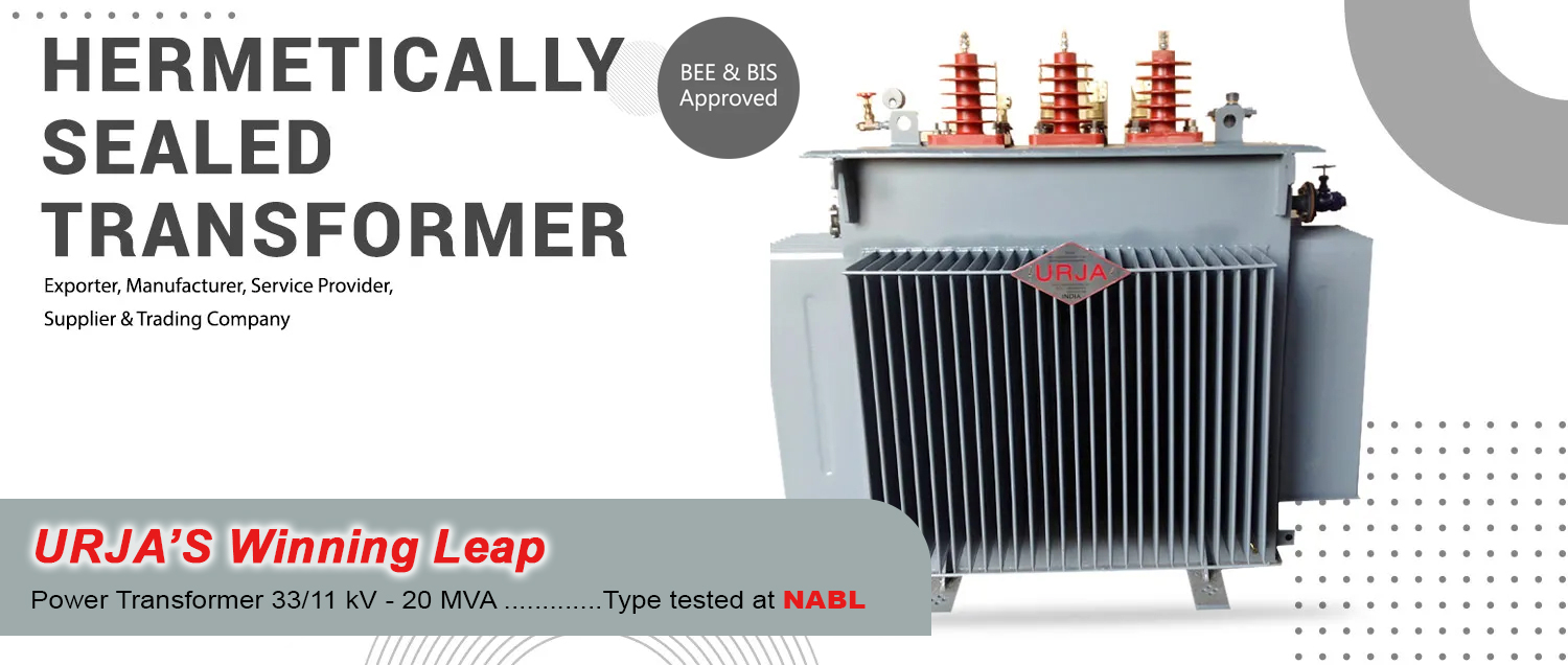
Heavy Duty Industrial Submerged Arc Furnace Transformer Manufacturing Facility

1. High Current & Electromagnetic Forces

Secondary currents in submerged arc smelting reach astronomical levels. The electrodynamic forces ($F \propto I^2$) generated during sudden electrode short circuits or slag bridge collapses can tear standard transformer windings apart. Urja Techniques utilizes high-density laminated pressboard insulation, self-locking radial spacers, and heavy-duty steel clamping frames to ensure absolute mechanical short-circuit withstand integrity verified by CPRI/ERDA testing standards.

2. Wide Secondary Voltage Regulation

Submerged arc furnace operation demands wide voltage variation to accommodate changing charge resistivity, electrode consumption, and process tap-to-tap cycles. Our SAF transformers incorporate integrated On-Load Tap Changers (OLTC) with booster transformer arrangements or auto-transformer regulation circuits, providing 17 to 33 discrete voltage steps without interrupting the high-current smelting arc.

3. Harmonic Stress & Stray Flux Losses

Non-linear arc resistance generates severe current harmonics that induce stray magnetic flux in the transformer tank walls, core clamps, and structural members. Urja Techniques mitigates hot-spot formation by incorporating non-magnetic stainless steel inserts, copper shielding plates, and transposed CTC (Continuously Transposed Conductors) in secondary windings.

4. Internal Delta Closure & Busbar Symmetry

To minimize heavy secondary current induction losses and inductance reactance ($X_L$), the delta closure of the 3-phase system is frequently carried out close to the furnace electrodes or internally inside the transformer tank. Urja Techniques engineers symmetrical low-inductance bus tube arrangements, ensuring balanced impedance across all three phases.
Custom Submerged Arc Furnace Transformer Solutions & Recommended Specifications

Tailored electrical architectures designed for specific smelting chemistries, plant capacities, and environmental conditions.

Smelting Application Typical Rating (MVA) Primary Voltage Range Secondary Voltage Range Cooling Class Regulation Method
Ferrosilicon (FeSi) & Silicon Metal 10 MVA - 45 MVA 11 kV / 22 kV / 33 kV 90 V - 240 V (High Secondary Current) OFWF / OFAF OLTC with Booster / Direct Tap
Silicomanganese (SiMn) & FeMn 6.3 MVA - 33 MVA 11 kV / 33 kV 100 V - 280 V ONAN / OFAF / OFWF On-Load Tap Changer (OLTC)
Ferrochrome (FeCr - HC & LC) 9 MVA - 36 MVA 11 kV / 33 kV 110 V - 320 V OFWF (Oil Forced Water Forced) OLTC (33 Steps)
Calcium Carbide (CaC2) 15 MVA - 60 MVA 22 kV / 33 kV / 66 kV 80 V - 220 V (Ultra-High Current) OFWF Water Cooled Busbar Internal Delta / Auto-Transformer
Non-Ferrous Slag Smelting (Copper/Nickel) 5 MVA - 25 MVA 11 kV / 22 kV / 33 kV 75 V - 250 V ONAN / OFAF Off-Circuit Tap Changer (OCTC) / OLTC

Product Recommendation: Heavy-Duty Liquid-Immersed SAF Transformer

For large-scale ferroalloy and silicon metal production units, Urja Techniques recommends our Liquid-Immersed Double-Wound SAF Transformer with Forced Oil Water (OFWF) Heat Exchangers. Featuring premium electrolytic copper windings insulated with thermally upgraded kraft paper, these units are vacuum dried and oil filled under high vacuum to eliminate partial discharge.


The secondary lead exits are arranged as water-cooled copper bus tubes or silver-plated copper bars projecting through heavy-duty non-magnetic brass or stainless steel gland plates. This prevents eddy current overheating while maintaining a hermetic, leak-proof seal against corrosive furnace atmospheres.


Get a Quote
Urja Techniques Submerged Arc Furnace Transformer Unit

Electrolytic Copper Bus Tubes

Custom fabricated high-purity copper busbar exits designed to handle up to 100,000 Amperes with low temperature rise and minimal skin effect losses during continuous round-the-clock furnace operation.

Robust Tank & Structural Integrity

Shot-blasted high-tensile steel tanks reinforced with external stiffeners to withstand internal vacuum pressure, mechanical transportation loads, and operational seismic forces.

Advanced Protection Systems

Equipped with multi-contact Buchholz relays, magnetic oil level gauges, sudden pressure relays, optical fiber temperature sensors (FOT), and winding temperature indicators (WTI) with SCADA outputs.

Future Procurement & Technological Trends in Smelting Transformers

How global decarbonization, AI predictive maintenance, and ester dielectric fluids are transforming SAF Transformer specification standards for the next decade.

Industrial Furnace Power Transformer Technology

1. Decarbonization & Green Steel Efficiency Imperatives

As global metallurgical operators face stringent carbon reduction goals (Scope 1 and Scope 2 emissions), transformer energy efficiency has shifted from a secondary consideration to a primary procurement metric. Modern SAF transformers must comply with total cost of ownership (TCO) evaluation models, where No-Load Losses ($P_0$) and Load Losses ($P_k$) are heavily capitalized over a 25-30 year lifespan.


Urja Techniques addresses this trend by using high-permeability, domain-refined Cold-Rolled Grain-Oriented (CRGO) silicon steel cores assembled with 45-degree mitered joints and step-lap stacking techniques. This reduces core losses by up to 18% and minimizes excitation currents under extreme over-voltage conditions.

2. Synthetic & Natural Ester Fluids

Replacing mineral insulating oil with high-fire-point ester fluids (K-class, flash point >300°C) is gaining rapid traction in indoor and high-hazard metallurgical plants. Ester fluids eliminate fire deluge system expenses, extend paper insulation thermal lifespan, and provide 100% biodegradability in environmentally sensitive zones.

3. IoT & AI-Driven Predictive Diagnostics

Global procurement teams now require SAF transformers equipped with real-time online Dissolved Gas Analysis (DGA), continuous moisture-in-oil tracking, and optical fiber hot-spot monitoring. Integrating these sensors into industrial SCADA and AI predictive maintenance platforms prevents catastrophic dielectric breakdown before furnace downtime occurs.

4. Harmonic-Resilient Hybrid Designs

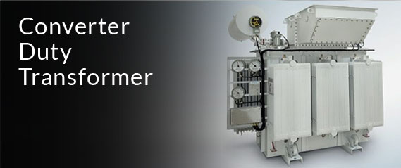
With the expansion of thyristor-controlled converter-fed submerged arc furnaces (DC smelting) and STATCOM-supported AC furnaces, transformers must handle extreme harmonic spectra without thermal overload. Urja Techniques engineers specialized K-factor and harmonic-attenuating shield windings specifically for converter-duty SAF plants.

Upgrade Your Smelting Plant Infrastructure

Consult with Urja Techniques' senior transformer design engineers to optimize your SAF transformer specifications for total energy efficiency and high operational uptime.

Get a Quote

Key Technical Questions International Buyers Ask AI & Senior Consultants

Direct, data-driven answers to complex engineering inquiries encountered during global procurement technical audits.

Q1: How do you prevent internal secondary busbar overheating caused by high current skin effect and proximity effect in a 30 MVA SAF Transformer?

Engineering Analysis: At secondary currents exceeding 30,000 Amperes, alternating magnetic fields force current to flow exclusively along the outer periphery of solid copper busbars (skin effect) and cause uneven current distribution between adjacent phases (proximity effect). This creates localized thermal hot spots that degrade transformer gaskets and oil insulation.

Urja Techniques Solution: We utilize hollow, water-cooled copper bus tubes or multi-strand transposed copper strips arranged in parallel interleaving geometric formations. Additionally, all tank exit plates through which heavy secondary leads pass are fabricated from non-magnetic stainless steel (AISI 304/316) or non-ferrous aluminum brass alloys to break eddy current magnetic loops.

Q2: What is the optimal voltage regulation scheme for a Submerged Arc Furnace Transformer: On-Load Tap Changer (OLTC) on Primary vs. Auto-Transformer / Booster Combination?

Engineering Analysis: Submerged arc furnaces demand very low voltage steps across a broad operating window (e.g., 100 V to 260 V). If a direct OLTC is placed on the high-voltage primary winding, the number of turns changes drastically, causing large variation in core flux density and secondary short-circuit impedance across different tap positions.

Urja Techniques Solution: For wide regulation ranges (above 50% voltage variation), we recommend an Auto-Transformer + Main SAF Transformer dual-tank or single-tank booster combination. The auto-transformer regulates the intermediate voltage supplied to the primary of the main furnace transformer, keeping the main core flux constant and maintaining uniform short-circuit impedance across all 33 tap steps. For smaller voltage ranges, direct high-voltage tap changers with constant flux regulation (CFR) are supplied to minimize capital cost.

Q3: How do you evaluate thermal endurance against repeated dead short-circuits caused by electrode scrap cave-ins?

Engineering Analysis: During smelting, conductive scrap or un-melted raw material can fall against the electrode, causing an instantaneous dead short-circuit (up to 8 to 10 times rated full-load current). The thermal energy ($I^2 t$) generated during the 2-3 seconds before circuit breaker tripping can char paper insulation and ignite transformer oil if not properly engineered.

Urja Techniques Solution: All Urja SAF transformers are designed with reduced current density in copper conductors (typically <2.8 A/mm²), thermally upgraded Class A/E insulation materials, and forced oil circulation directed straight through radial cooling ducts within the winding stacks. Thermal short-circuit calculations strictly adhere to IEC 60076-5 standards and are verified through short-circuit dynamic force modeling.

30+ Years of Manufacturing Excellence: The Urja Techniques Quality Guarantee

Combining precision Indian electrical engineering with rigorous international quality standards for global smelting installations.

World-Class Manufacturing Base in Mumbai, India

Founded in 1991 in Wadala, Mumbai, Urja Techniques (India) Pvt. Ltd. has grown into an international powerhouse in specialty industrial transformer manufacturing. Operating from an ISO 9001:2015, ISO 14001:2015, and BS OHSAS 18001 certified facility, we design, build, and test heavy-duty furnace transformers engineered to withstand the world's most unforgiving industrial environments.


With over 40% of our total revenue derived from international exports, our transformers are currently powering metallurgical, utility, mining, and chemical projects in more than 40 countries across Africa, the Middle East, Europe, and Southeast Asia.


30+
Years Manufacturing Excellence
40+
Countries Exported To
100%
CPRI / ERDA Type Tested
ISO
9001 & 14001 Certified

In-House Temperature Rise Test Facility

Our manufacturing plant features an advanced in-house full-load temperature rise testing setup—one of BIS and IEC's most stringent type tests—ensuring thermal compliance prior to dispatch.

ERDA & CPRI Type Test Verification

Our transformers undergo full type testing at independent nationally accredited laboratories, including ERDA (Electrical Research and Development Association) and CPRI (Central Power Research Institute).

Global Standards Compliance

Fully manufactured in compliance with international standard specifications including IEC 60076, IS 2026, IS 1180, ANSI/IEEE C57, and BS standards.

Frequently Asked Questions: Submerged Arc Furnace Transformer Procurement

Addressing technical, commercial, and operational queries from global EPC contractors and plant managers.

1. What is the fundamental difference between an Electric Arc Furnace (EAF) Transformer and a Submerged Arc Furnace (SAF) Transformer? +

While both are industrial furnace transformers, their operational dynamics differ significantly:

  • EAF Transformers (Steel Smelting): Operate with open arcs striking directly onto scrap steel. They experience violent open-arc ignition, severe voltage flicker, and frequent open-circuit to short-circuit transitions as scrap shifts.
  • SAF Transformers (Ferroalloy / Silicon Smelting): Operate with electrodes continuously submerged inside a solid charge bed. The electrical load is a hybrid combination of submerged arc heating and charge resistance heating. The load is more continuous, but secondary currents are exceptionally higher (up to 100+ kA), requiring continuous high-current thermal management and wide low-voltage step regulation.
2. Why is water cooling (OFWF - Oil Forced Water Forced) preferred for SAF Transformers? +

Submerged arc furnace buildings are hot, dusty environments contaminated with conductive metal dust, silica fume, and slag particles. Air-cooled radiators (ONAF) can quickly clog with airborne particulate matter, reducing heat dissipation efficiency.

An OFWF (Oil Forced Water Forced) system uses compact shell-and-tube or plate-type heat exchangers where oil is pumped through a closed water-cooled heat exchanger. This isolates the transformer cooling circuit from ambient atmospheric dust, provides extremely compact footprints near the furnace hall, and enables precise oil temperature regulation regardless of ambient air temperature.

3. How does internal delta closure benefit a Submerged Arc Furnace installation? +

In a 3-phase high-current AC system, carrying secondary current in phase connections to an external delta closure outside the transformer house creates significant inductive voltage drop ($V_{drop} = I \times X_L$) and high magnetic field radiation.

By executing the delta closure internally inside the transformer tank or directly at the secondary bushings, the current carried in the long flexible leads to the electrodes is reduced by a factor of $\sqrt{3}$ ($I_{line} = I_{phase} / \sqrt{3}$). This reduces line copper losses ($I^2 R$) by 66%, improves plant power factor, and lowers reactive impedance in the heavy secondary bus circuit.

4. What primary parameters must be provided to receive an accurate technical quotation? +

To prepare an optimized electrical and structural design quotation, our engineering team requires:

  • Rated Transformer Capacity (MVA or kVA)
  • Primary Grid Voltage (e.g., 11 kV, 22 kV, 33 kV, 66 kV) and frequency (50 Hz / 60 Hz)
  • Secondary Voltage Range (Maximum, Nominal, and Minimum tapping voltages)
  • Maximum Continuous Secondary Current (Amperes)
  • Smelting Product / Process Type (Ferrosilicon, SiMn, FeCr, Silicon Metal, Calcium Carbide)
  • Preferred Cooling Type (ONAN, OFAF, OFWF)
  • Tap Changer Preference (On-Load Tap Changer vs. Off-Circuit Tap Changer)
  • Site Ambient Conditions (Altitude, Ambient Temperature Range, Indoor/Outdoor Installation)
5. What type-test certificates and documentation are supplied with Urja Techniques transformers? +

Every transformer manufactured by Urja Techniques is dispatched with a comprehensive Quality Assurance Dossier including Routine Test Reports (Winding Resistance, Turns Ratio, Vector Group, Insulation Resistance, Applied Voltage, Induced Overvoltage, No-Load & Load Loss Measurements).

Type Test certificates from independent ISO/IEC 17025 accredited testing laboratories (CPRI & ERDA) covering Temperature Rise Tests, Lightning Impulse Withstand Tests, Short-Circuit Withstand Capability, and Acoustic Noise Level Tests are provided upon request.

6. What is the typical manufacturing lead time for custom Submerged Arc Furnace Transformers? +

Depending on MVA rating, voltage complexity, and OLTC specification, typical delivery timelines range between 12 to 20 weeks from technical drawing approval. Fast-track production options are available for urgent plant overhaul or replacement projects.

Explore our complete range of specialized industrial furnace, converter, power, and distribution transformer solutions.

Ready to Partner with India's Leading Transformer Exporter?

Get in touch with our expert engineering sales team in Mumbai to receive a customized technical specification proposal and competitive commercial quote.

Get a Quote