Solar Application Transformer Engineering & Procurement Guide

An authoritative, technical, and commercial analysis on selecting, step-up integration, harmonic mitigation, and sourcing high-efficiency Solar Application Transformers for utility-scale photovoltaic infrastructure.

IEC 60076-16 Compliant IEEE C57.159 Standards Multi-Winding Step-Up Architecture K-Factor Rated & THD Protection ISO 9001:2015 Manufacturer
Send an Inquiry

Navigating Solar Application Transformer Selection in Utility-Scale PV Plants

As the global transition toward renewable energy accelerates, solar photovoltaic (PV) power plants are rapidly scaling from megawatt (MW) installations to multi-gigawatt (GW) utility projects. At the core of every grid-connected solar power generation system lies a critical asset: the Solar Application Transformer (also known as a Solar Step-Up Transformer or Inverter Duty Transformer). Unlike conventional distribution transformers operating under stable 50/60 Hz sinusoidal loads, solar application transformers endure uniquely harsh operational environments characterized by high-frequency harmonics, non-linear inverter outputs, solar irradiance variability, thermal cycling, and continuous DC bias currents.

For global procurement managers, EPC contractors, project developers, and electrical engineers, specifying a solar application transformer requires going far beyond simple MVA ratings and primary/secondary voltage ratios. Selecting an incorrectly rated or poorly engineered transformer leads to accelerated insulation degradation, severe core heating from harmonic eddy currents, premature transformer failure, and millions of dollars in uncompensated plant downtime. This comprehensive engineering guide explores the technical parameters, structural design requirements, multi-winding topologies, procurement trends, and future innovations of Solar Application Transformers manufactured by Urja Techniques (India) Pvt. Ltd.

Why Standard Distribution Transformers Fail in Solar PV Applications

A frequent error made during preliminary project budgeting is specifying standard distribution or general power transformers for solar PV stations. Standard distribution transformers are designed for continuous, linear sinusoidal loads with minimal harmonic contamination and predictable thermal cycles. In contrast, grid-tie solar PV systems introduce severe stresses:

  • Non-Linear Harmonic Stresses: Pulse-Width Modulation (PWM) solar inverters inject high-frequency harmonic voltages and currents (typically 5th, 7th, 11th, 13th, and higher order switching frequencies up to several kHz). These harmonics cause severe stray load losses, skin-effect copper losses, and excessive localized core heating.
  • Thermal Cycling & Intermittent Solar Irradiance: Solar transformers experience total load fluctuations every day—ramping from zero load at dawn to 100% overload capacity during peak solar noon, and cooling down rapidly during cloud transients or nightfall. This thermal expansion and contraction subjects internal mechanical clamping, gaskets, and insulation papers to high mechanical fatigue.
  • DC Component Injection: Slight asymmetry in inverter IGBT switching can cause tiny DC current offsets to flow into the transformer's low-voltage (LV) windings. Even sub-ampere DC bias currents drive transformer magnetic cores toward saturation, leading to elevated magnetizing current, intense audible noise, and severe core loss spikes.
  • Multi-Inverter Isolation Challenges: Modern central inverter stations combine multiple inverter modules into a single transformer tank via dual-LV or triple-LV secondary windings. Without precise electrostatic shielding and phase-decoupled winding geometry, circulating cross-currents between inverters can trip inverter protection relays and compromise system efficiency.
Technical Architecture & Multi-Winding Engineering of Solar Transformers

To withstand the complex electrical environment of utility-scale PV solar fields, a true Solar Application Transformer must be designed strictly in accordance with IEC 60076-16 (Transformers for wind turbine and solar power application) and IEEE C57.159 (Guide for Application of Transformers in Distributed Photovoltaic Power Generation Systems).

1. Multi-Winding Low Voltage (LV) Configuration

To optimize Levelized Cost of Energy (LCOE) and reduce balance-of-plant footprint, modern solar block designs utilize multi-inverter configurations. Instead of connecting one transformer per inverter, a single Solar Application Transformer features two, three, or four separate LV windings (e.g., Dy11y11 or Dy11y11y11 vector configurations) stepping up voltage to a single High Voltage (HV) grid connection (e.g., 11kV, 22kV, 33kV, or 66kV). Urja Techniques engineers these windings with strict impedance symmetry to ensure balanced power flow from each inverter block.

2. Electrostatic Shielding & Harmonic Isolation

To prevent high-frequency inverter switching transients, voltage spikes, and common-mode noise from coupling into the medium-voltage grid, grounded copper electrostatic shields are placed between the LV and HV windings. Furthermore, custom K-factor ratings (K-4, K-9, or K-13 depending on inverter THD profile) are incorporated into conductor sizing to prevent thermal runaway caused by harmonic eddy currents.

Key Technical Comparison: Standard Power Transformer vs. Solar Application Transformer

Engineering Parameter Standard Power / Distribution Transformer Urja Solar Application Transformer
Design Standard Compliance IS 2026 / IEC 60076-1 IEC 60076-16 / IEEE C57.159 / IS 2026
Load Profile & Duty Cycle Continuous steady load, low fluctuation Dynamic thermal cycling, peak solar noon loads
Harmonic Tolerance (THD) Standard sinusoidal (THD < 5%) High non-linear harmonic load (K-Factor 4 to 13+)
DC Bias Resistance Not rated for DC current offset Core engineered for DC offset immunity without saturation
Winding Topology Single LV to Single HV Winding Multi-LV (Dual/Triple/Quad) decoupled windings
Electrostatic Shielding Optional / Rare Fitted between HV & LV windings as standard
Insulation Thermal Class Class A (105°C) standard Enhanced Class A, F or H with high thermal margin
Cooling Medium Options ONAN Mineral Oil ONAN / ONAF Mineral Oil, Natural Ester (FR3), or VPI Dry Type

Recommended Solar Application Transformer Product Range

At Urja Techniques (India) Pvt. Ltd., we offer a specialized portfolio of high-efficiency step-up and inverter duty transformers specifically tailored to solar PV plants, rooftop commercial arrays, microgrids, and utility-scale energy storage systems (BESS). Below are our recommended transformer solutions backed by proven performance across international solar installations.

Solar Application Transformer for Renewable Power Plants

Oil-Immersed Solar Step-Up Transformer

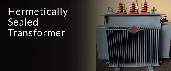
Designed for ground-mounted utility-scale PV plants. Features multi-winding input, hermetically sealed or conservator design, and superior oil convection cooling for harsh ambient temperatures up to 55°C.

Capacity: 1 MVA to 12.5 MVA HV Voltage: Up to 33kV / 66kV LV Windings: Dual (Dy11y11) / Triple Standard: IEC 60076-16
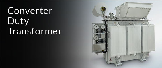
Converter Duty Solar Inverter Transformer

Heavy Duty Inverter & Converter Transformer

Specifically engineered for multi-megawatt central solar inverters and battery storage (BESS) bi-directional converters. Built with electrostatic shields and extra thermal margin for harmonic suppression.

Capacity: 500 kVA to 10 MVA Vector Group: Dy11y11 / Ynd11 K-Factor: K-4, K-9, K-13 Testing: ERDA / CPRI Tested
Solar Compact Substation Skid Package

Compact Substation for Solar Fields

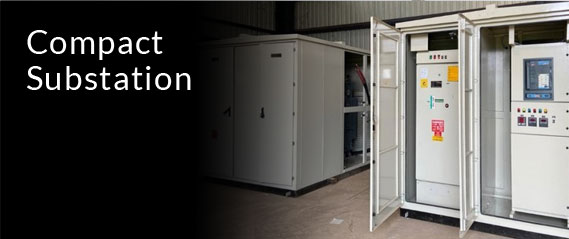
An integrated, factory-assembled package combining a solar step-up transformer, SF6 or vacuum ring main unit (RMU), and LV inverter switchgear mounted on a common structural steel skid.

Capacity: Up to 6.3 MVA Skid Package Enclosure: IP54 / IP55 Outdoor Duty Enclosure Material: Galvanized / FR3 Filled Footprint: Ultra-Compact Modular
VPI Dry Type Solar Transformer for Commercial Rooftops

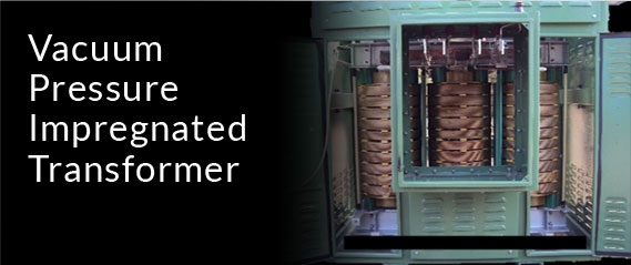
VPI Dry Type Solar Transformer

Vacuum Pressure Impregnated (VPI) dry-type transformer ideal for rooftop solar installations, commercial complexes, and environmentally sensitive zones requiring high fire safety.

Capacity: 250 kVA to 3.15 MVA Insulation Class: Class H (180°C) Fire Safety: Self-Extinguishing Maintenance: Zero Liquid Leakage
High Voltage Grid Step-Up Solar Power Transformer

Grid Coupling Solar Power Transformer

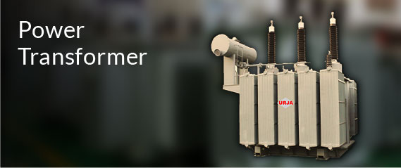
High-voltage main step-up transformers designed to elevate pooled solar plant MV busbar voltages (33kV) to transmission grid levels (66kV, 110kV, or 132kV) equipped with On-Load Tap Changers (OLTC).

Capacity: Up to 50 MVA Tapping: OLTC / Off-Circuit Tap Changer Bushings: RIP / OIP High Voltage Loss Level: Super Low Loss CRGO
Solar Neutral Grounding and Earthing Transformer

Solar Neutral Earthing Transformer

Zig-zag (Zn) earthing transformer designed to provide a artificial neutral point for ungrounded solar collector networks, preventing phase-to-ground overvoltages and facilitating ground fault detection.

System Voltage: 11kV, 22kV, 33kV Winding: Zn / Znd11 Current Rating: Tailored Fault Duration Application: Solar PV Substation

Global Procurement Trends in Solar Application Transformers

Procurement practices for solar transformers have evolved significantly over the past three years. Driven by tighter grid codes, higher inverter DC bus voltages, and strict ESG requirements, international solar buyers and EPC contractors are adopting new technical evaluation metrics:

1. Transition to 1500V DC Architecture & Higher Inverter AC Output Voltages

Modern utility-scale solar farms have universally shifted from legacy 1000V DC strings to 1500V DC systems. This transition increases central inverter AC output voltages from 315V / 400V up to 600V, 630V, 690V, or 800V AC. Global procurement specifications now demand transformers capable of handling higher dielectric stress, increased impulse withstand levels (BIL), and specialized insulation systems capable of resisting continuous high-frequency voltage oscillations.

2. Rapid Adoption of Biodegradable Natural Ester Fluids (FR3)

Environmental risk management and fire prevention are now top procurement considerations. Major solar EPC developers in Europe, North America, and Australia are replacing mineral oil with Natural Ester (K-class) insulating fluids like Cargill FR3. Natural ester fluids offer a flash point exceeding 300°C (compared to 140°C for mineral oil), are 100% biodegradable within 28 days, and allow transformers to operate at higher temperature rises without degrading the cellulose insulation papers.

3. Factory-Integrated Modular Skid Substations

Rather than purchasing individual components (transformers, RMUs, circuit breakers, and auxiliary distribution boards) separately, global procurement teams are specifying Integrated Solar Skid Solutions. Pre-wired, factory-tested skids drastically reduce site installation labor, eliminate field wiring errors, and minimize commission lead times for solar projects in remote desert or mountain locations.

4. Total Cost of Ownership (TCO) & No-Load Loss Evaluation Formulas

Savvy global solar buyers no longer evaluate bids strictly on initial purchase price (CAPEX). Instead, capitalization formulas for No-Load Losses (A-factor, $/W) and Load Losses (B-factor, $/W) are embedded into tender evaluation. Because solar transformers sit energized at zero power output during night hours, minimizing core no-load loss using high-grade grain-oriented silicon steel (CRGO) or amorphous core metal yields substantial operational savings over a 25-year plant life.

Future Development Trends in Photovoltaic & Renewable Transformers

Looking ahead toward the next decade of renewable grid integration, the design of Solar Application Transformers is undergoing a technological revolution. Key trends shaping future transformer engineering include:

1. Hybrid Solar + Battery Energy Storage System (BESS) Bi-Directional Power Flow

As solar power plants are increasingly paired with utility-scale Battery Energy Storage Systems (BESS), solar transformers must handle continuous bi-directional power flow. Transformers must step up solar power to the grid during peak daytime production, while stepping down grid power to charge battery banks during off-peak hours. This requirement demands symmetrical magnetic circuit design, enhanced tap-changer endurance, and advanced thermal modeling.

2. AI-Powered Smart Transformer Monitoring & Predictive Diagnostics

The integration of IoT sensor networks and AI analytics is transforming transformer maintenance from reactive to predictive. Future-ready solar transformers manufactured by Urja Techniques feature digital online DGA (Dissolved Gas Analysis) sensors, fibre-optic direct winding temperature sensors, online moisture monitors, and smart bush monitoring units. These sensors feed real-time health data to central SCADA systems, enabling AI algorithms to predict insulation aging, detect early partial discharge, and prevent catastrophic field failures.

3. Ultra-Low Loss Amorphous Metal Core Technology

With global net-zero mandates tightening, transformer efficiency regulations (such as EU Ecodesign Tier 2 and Indian BIS Energy Efficiency Levels) are becoming stricter. The introduction of amorphous alloy core ribbons in solar application transformers reduces no-load losses by up to 70-75% compared to conventional CRGO steel cores, significantly reducing parasitic energy consumption of solar stations during non-generating periods.

Frequently Asked Questions by Global Solar Procurement Buyers

Below are authoritative answers to the most common technical and commercial queries submitted to Urja Techniques by international procurement officers, solar EPC contractors, and grid interconnection consultants.

Q1: What is the primary difference between an Inverter Duty Transformer and a standard Solar Step-Up Transformer?

Answer: An Inverter Duty Transformer is specifically designed to connect directly to the low-voltage output of solar inverters. It is engineered with specialized features to handle non-sinusoidal AC waveforms, high-frequency PWM switching harmonics, DC voltage offsets, and electrostatic shields between windings. A standard Solar Step-Up Transformer refers generally to any transformer in a solar plant stepping up voltage (whether from inverter output to medium voltage or from medium voltage to high-voltage transmission). All inverter duty transformers are step-up transformers, but they possess enhanced harmonic tolerance and multi-winding decoupling required by solar inverters.

Q2: Why are multi-winding LV configurations (Dy11y11) preferred in solar power plant design?

Answer: Multi-winding LV configurations allow multiple central solar inverters (e.g., two 2.5 MW inverters) to connect to a single step-up transformer (e.g., 5 MVA Dy11y11) feeding a 33kV grid line. This setup cuts transformer count by 50%, significantly reduces civil foundation works, decreases medium-voltage switchgear requirement, minimizes cabling losses, and optimizes overall plant footprint and LCOE.

Q3: How does Urja Techniques mitigate harmonic heating in Solar Application Transformers?

Answer: We apply advanced finite element analysis (FEA) to calculate stray magnetic fields caused by high-order harmonics. To mitigate heating, we utilize continuously transposed conductors (CTC) or multiple transposed foil windings to eliminate skin effect, specify K-Factor ratings (K-4 to K-13+), enlarge cooling ducts for uniform oil/air circulation, and incorporate high thermal class insulation materials that resist accelerated thermal degradation.

Q4: What compliance standards should international buyers look for when procuring solar transformers?

Answer: Global procurement buyers must ensure compliance with IEC 60076-16 (specifically dedicated to wind turbine and solar transformers), IEEE C57.159 (guide for solar PV transformers), IS 2026 / IS 1180 (Indian standards), and relevant regional grid code requirements. Additionally, type test certificates from independent NABL-accredited laboratories like CPRI (Central Power Research Institute) or ERDA (Electrical Research and Development Association) for short-circuit withstand, impulse voltage withstand, and temperature rise tests are critical verification credentials.

Q5: Can Urja Techniques manufacture Solar Application Transformers with Natural Ester (FR3) fluid?

Answer: Yes. Urja Techniques manufactures both mineral oil-filled and natural ester (biodegradable FR3) filled solar application transformers. Natural ester transformers provide high fire safety (K-class, flash point > 300°C), extend insulation lifespan, and allow eco-friendly installation near agricultural zones or water bodies where oil leak spillages are strictly prohibited.

Q6: What lead times and export packaging standards does Urja Techniques provide for overseas solar projects?

Answer: Typical manufacturing lead time ranges from 6 to 12 weeks depending on MVA rating, voltage class, and custom engineering requirements. For global exports to Africa, the Middle East, Europe, and Asia, transformers are fitted with nitrogen gas padding, sealed moisture indicators, sea-worthy heavy timber crating, and anti-corrosion marine coatings suitable for ocean transport and desert storage.

Urja Techniques: Engineering Excellence & Corporate Strengths

Established in 1991 in Mumbai, India, Urja Techniques (India) Pvt. Ltd. brings over 30+ years of domain experience to the global electrical equipment manufacturing sector. Built on a foundation of uncompromised engineering quality, technical precision, and robust E-E-A-T (Experience, Expertise, Authoritativeness, and Trustworthiness) principles, Urja Techniques is recognized as a premiere transformer supplier to state electricity boards, global EPC contractors, and multinational corporations.

30+
Years of Manufacturing Mastery
40%+
Revenue Derived From Exports
40+
Global Export Destinations
ISO
9001:2015 & 14001:2015 Certified

Our Core Corporate Strengths:

  • Globally Accredited Quality Management: ISO 9001:2015, ISO 14001:2015, and OHSAS 18001 certified manufacturing facilities. All transformer designs undergo rigorous quality assurance protocols at every stage—from raw material core slitting to vacuum oil filling.
  • In-House Type Testing Facility: Our state-of-the-art testing bay includes an in-built Temperature Rise Test Facility—one of the most critical BIS and IEC type test requirements for power transformers—ensuring every unit delivers validated thermal performance before dispatch.
  • Type Tested by CPRI & ERDA: Our transformers have successfully completed comprehensive type testing at leading independent national testing laboratories, including CPRI (Central Power Research Institute) and ERDA (Electrical Research & Development Association), for short-circuit withstand withstand capability and high-voltage lightning impulse tests.
  • Custom Engineering & Vector Matching: Every Solar Application Transformer is custom-built to match exact inverter electrical parameters (ABB, SMA, Huawei, Sungrow, Schneider, Power Electronics, etc.), grid step-up voltages, environmental conditions, and enclosure constraints.
  • Extensive International Footprint: With over 40% of total revenue generated from international markets, our transformers power utility networks, industrial complexes, and solar installations across Africa, the Middle East, Europe, South America, and Asia.

Accelerate Your Solar PV Project With Urja Engineering

Looking for custom-engineered, IEC 60076-16 compliant Solar Application Transformers or integrated compact skid substations for your upcoming utility-scale solar or energy storage installation? Speak directly with our senior application engineers today.

Send an Inquiry