Featured Industrial & Renewable Power Transformers
Explore our CE & IEC certified transformers engineered for utility grids, wind farms, solar substations, and heavy industrial installations worldwide.
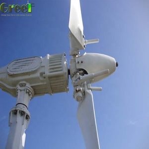
Aluminium Body Small Wind Turbine for Farm
Get a Quote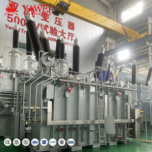
Yawei Manufacturer Price 10 MVA 15MVA 20MVA 67KV 69KV 33KV Power Transformer Copper Winding 60hz Dyn11
Get a Quote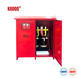
Wind Turbine Generator Isolation Transformer 800KVA Three Phase IP65 Protection CE Certified for Renewable Energy Systems
Get a Quote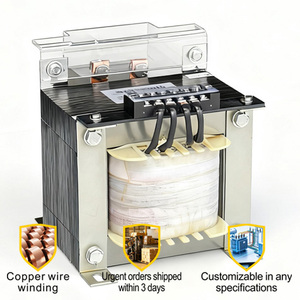
5KVA 10kVA Single Phase Control Transformer 110/220V To 36/48V For Packaging Machinery Pure Copper Winding CE ISO
Get a Quote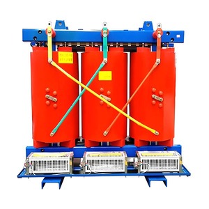
Customizable Fire Prevention Buildings Use Isolation Copper Winding Three Phase 33KV 35KV 38.5KV Wind Turbine Dry Transformer
Get a Quote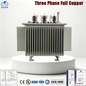
Distribution Transformer 100kVA 10/0.4kV Three Phase Oil Immersed Copper Winding IEC CE Certified 50Hz For Utility Grid
Get a Quote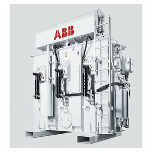
ABB (Hitachi Energy) Offshore Wind Turbine Transformer5-25MVA 66-72.5KV IEC Genuine
Get a Quote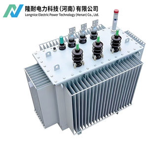
S11 3 Phase Oil Immersed Distribution Transformer 10kV 0.4kV 100% Copper Winding Power Transformer
Get a QuoteEngineering Principles & System Protection Dynamics of Earthing Transformers
In electrical power transmission and medium-voltage (MV) distribution networks, ungrounded delta-connected systems or isolated-neutral wye systems present substantial risk of severe overvoltages during single line-to-ground (SLG) faults. An Earthing Transformer (also referred to as a Grounding Transformer or Neutral Grounding Transformer - NGT) is an indispensable auxiliary device designed specifically to establish a neutral point for an ungrounded three-phase power system, facilitating continuous fault current return paths and stabilizing system neutral potential.
Without an established neutral point, transient phase-to-ground arcing faults in delta networks generate arcing grounds, inducing destructive transient overvoltages up to 400% of nominal system voltage. This dielectric stress causes catastrophic breakdown of cable insulation, transformer windings, and switchgear components. A properly engineered, CE-certified earthing transformer mitigates these hazards by providing low zero-sequence impedance ($Z_0$) to ground fault currents while presenting extremely high positive ($Z_1$) and negative sequence ($Z_2$) impedance to normal continuous operating currents.
Core Electrical Vectors: Zig-Zag (Zn) vs. Star-Delta (Ynd) Topology
Industrial transformer designers employ two primary vector topologies when creating neutral grounding points for ungrounded networks:
1. Interconnected Star / Zig-Zag Winding (Zn)
The Zig-Zag topology utilizes six co-wound electromagnetic coils on a three-phase core. Each core phase limb houses two distinct winding halves connected in reverse polarity to adjacent limbs. During balanced three-phase system operation, magnetic fluxes generated by normal positive and negative sequence currents vectorially cancel out within each limb, ensuring virtually zero magnetizing current draw. Upon an SLG fault, zero-sequence fault currents flow in phase across all three legs, encountering minimal zero-sequence reactance ($X_0$), allowing rapid actuation of protective relays.
2. Wye-Delta Grounding Winding (Ynd11 / Ynd1)
The Wye-Delta alternative incorporates a star-connected primary winding with an accessible neutral point tied directly or through a neutral grounding resistor (NGR) to earth, paired with a closed delta secondary winding. The closed delta provides a low-impedance circulating path for zero-sequence currents. While mechanically robust, the Ynd layout requires a two-winding construction, rendering it physically larger and costlier than a dedicated single-winding Zig-Zag earthing unit of equivalent thermal rating.
Zero-Sequence Impedance ($Z_0$) & Short-Time Thermal Rating Engineering
The thermal design of an earthing transformer differs fundamentally from continuous-duty power transformers. Because ground faults are rapidly isolated by high-speed circuit breakers, earthing transformers are rated for short-duration fault thermal withstand capacities—typically rated for 10 seconds, 30 seconds, or 60 seconds under maximum fault current conditions ($I_k''$).
The key design parameter is the zero-sequence impedance per phase ($Z_0 = R_0 + jX_0$). Precision electromagnetic calculation ensures that $Z_0$ limits ground fault current magnitude to prevent core saturation, thermal degradation of copper conductors, and mechanical deformation of coil structures due to electrodynamic forces during asymmetric short circuits.
Comparative Matrix: Oil-Immersed vs. Vacuum Pressure Impregnated (VPI) vs. Cast Resin
| Engineering Parameter | Oil-Immersed Earthing Transformer | VPI Dry-Type Earthing Transformer | Cast Resin (CRT) Earthing Unit |
|---|---|---|---|
| Cooling Medium / Class | ONAN / ONAF Mineral Oil or Ester Fluid | AN / AF Class H (180°C) Insulation | AN / AF Class F (155°C) Epoxy Resin |
| Voltage Class Range | Up to 69 kV / 72.5 kV Class | Up to 35 kV / 38.5 kV Class | Up to 35 kV Class |
| Fire Safety & Toxicity | Requires oil catch basin / fire suppression | Self-extinguishing, Zero Toxic Fumes | Non-flammable, High Fire Resistance |
| Short-Time Thermal Rating | 10s, 30s, 60s (Up to 3000A Neutral) | 10s, 30s (Up to 2000A Neutral) | 10s, 30s (Up to 2500A Neutral) |
| Environmental Protection | IP55 to IP65 Hermetically Sealed Tank | IP20 to IP44 NEMA Enclosures | IP23 to IP54 Reinforced Enclosure |
| Primary Application | Outdoor Substations, Wind Farms, Utilities | Indoor Power Plants, Packaging Plants | Offshore Platforms, Metros, Data Centers |
State-of-the-Art Manufacturing Capabilities & Global Credentials
Founded in 1991, Urja Techniques (India) Pvt. Ltd. stands as a preeminent global manufacturer and exporter of energy-efficient transformers, headquartered in Mumbai, Maharashtra. With over 30 years of specialized manufacturing experience, our company operates advanced engineering facilities compliant with international quality management systems including ISO 9001:2015, ISO 14001:2015, and OHSAS 18001.
Rigorous Type Testing
Every earthing transformer design undergoes comprehensive routine, type, and special testing at internationally accredited third-party laboratories, including the Central Power Research Institute (CPRI) and the Electrical Research and Development Association (ERDA), guaranteeing strict compliance with IEC 60076 and IS 2026.
In-House Testing Bay
Our Mumbai facility is equipped with an integrated modern testing bay featuring automated loss measurement systems, high-voltage impulse generators, partial discharge detectors, and an in-built temperature rise testing rig—allowing 100% full-load verification before factory dispatch.
Global Footprint
Driven by strict engineering standards, over 40% of our production volume is exported across 40+ countries in Europe, the Middle East, Africa, and Southeast Asia, serving utility boards, EPC contractors, and multinational industrial conglomerates.
Future Procurement Trends & Technology Trajectory (2025-2030)
As the global power grid accelerates its transition toward renewable generation, microgrids, and high-voltage direct current (HVDC) interconnectors, procurement requirements for grounding systems and earthing transformers are undergoing a profound transformation. Electrical procurement managers and grid engineers must align their procurement strategies with four key market trends:
1. Renewable Energy & Offshore Wind Integration
Utility-scale solar PV plants and offshore wind farms utilize floating or ungrounded delta collector networks operating at 33kV to 66kV. Earthing transformers designed for these facilities must incorporate high impulse withstand levels (BIL up to 325 kV) and severe environmental weatherproofing (C5-M anti-corrosion coatings, IP65 sealings) to endure marine and high-humidity salt-spray atmospheres.
2. Biodegradable Ester Fluids Replacing Mineral Oil
Environmental regulations and fire containment mandates are driving rapid replacement of traditional mineral oil with natural and synthetic ester fluids (such as Midel 7131 or FR3). Ester fluids offer fire points exceeding 300°C (K-class fluids) and 100% biodegradability, allowing earthing transformers to be installed in environmentally sensitive zones without costly secondary containment basins.
3. Smart Grid IoT & Fiber-Optic Condition Monitoring
Modern CE-certified grounding transformers are increasingly specified with integrated Fiber-Optic Temperature Sensors (FOTS), continuous neutral current monitoring CTs, and online Dissolved Gas Analysis (DGA) sensors. Real-time telemetry feed into SCADA systems provides early warning of insulation breakdown during repetitive transient fault events.
4. Compact & Modular Substation Integration
Urban density demands smaller substation footprints. Factory-integrated earthing transformers co-packaged with Neutral Grounding Resistors (NGRs), disconnect switches, and current transformers inside skid-mounted, weatherproof compact enclosures are rapidly replacing standalone sub-station components.
Frequently Asked Questions (FAQ) for Engineering Buyers
Q1: Why is a CE Certification crucial for Earthing Transformers installed in European & International markets?
The CE Mark certifies compliance with essential European Union directives, specifically the Low Voltage Directive (LVD 2014/35/EU) and Electromagnetic Compatibility (EMC) Directive 2014/30/EU. For procurement engineers, CE certification verifies that the transformer design satisfies rigorous electrical safety, insulation clearance, thermal rise limits, and structural integrity mandates under EN 60076 standards, facilitating seamless customs clearance and grid interconnection globally.
Q2: How do you calculate the required Zero-Sequence Impedance ($Z_0$) for a Zig-Zag Earthing Transformer?
Zero-sequence impedance is calculated based on the maximum allowable ground fault current ($I_g$) and the phase-to-neutral system voltage ($V_{pn}$):
Z_0 = (3 * V_pn) / I_g
Engineers adjust the turn ratios, core window geometry, and inter-winding magnetic spacing during manufacturing to achieve the exact target $Z_0$ (expressed in ohms per phase) required to trip protective ground-fault relays without over-stressing system components.
Q3: What is the difference between an Earthing Transformer and a Standard Power Distribution Transformer?
A standard power distribution transformer continuously transfers energy between voltage levels (e.g., 33kV to 400V) under continuous kVA ratings. An earthing transformer's primary purpose is to provide a neutral reference point for neutral-less systems (such as delta windings). It carries negligible magnetizing current under normal conditions and is designed structurally to withstand severe short-time thermal and dynamic stresses during ground faults (typically rated for 10s or 30s duty cycles).
Q4: Can an Earthing Transformer supply auxiliary local power loads simultaneously?
Yes. By adding a star-connected or delta-connected secondary auxiliary winding to the earthing transformer core (known as an Earthing Transformer with Auxiliary Winding), the unit can simultaneously provide system neutral grounding while supplying continuous low-voltage station auxiliary power (e.g., 415V/230V for substation lighting, battery chargers, and cooling fans).
Q5: What short-circuit duration withstand times should be specified during procurement?
Standard international specifications (IEC 60076-6 / IEEE C57.121) define standard short-time thermal ratings of 10 seconds, 30 seconds, or 60 seconds. For systems with fast-acting numerical protection relays and breaker trip times under 500ms, a 10-second thermal rating is often selected. For remote substations or industrial networks with delayed backup protection, a 30-second or 60-second rating is recommended.
Q6: How is a Neutral Grounding Resistor (NGR) integrated with an Earthing Transformer?
The neutral terminal (N) brought out from the Zig-Zag or Star primary winding of the earthing transformer is connected in series with a Neutral Grounding Resistor (NGR) to earth. The NGR restricts the line-to-ground fault current to a predetermined safe value (e.g., 100A, 200A, or 400A), limiting transient overvoltages while preventing localized damage at the fault location.
Q7: What factory acceptance tests (FAT) are mandatory before dispatch?
Factory Acceptance Testing includes Routine Tests: Winding Resistance Measurement, Voltage Ratio & Vector Group Verification, Short-Circuit Impedance & Zero-Sequence Impedance Measurement, Separate-Source AC Voltage Withstand, Applied Overvoltage / Induced Overvoltage Testing, and Insulation Resistance (Megger) Test. Type tests such as Temperature Rise and Full-Wave Lightning Impulse testing are performed on prototype or representative production units.
Q8: Why choose Urja Techniques (India) Pvt. Ltd. as your OEM earthing transformer supplier?
Urja Techniques combines over three decades of precision electrical engineering, ISO-certified manufacturing controls, full CPRI/ERDA type-test validations, competitive direct-factory pricing, and robust global export logistics (supplying 40+ countries). Our custom design capabilities ensure exact zero-sequence impedance matching tailored to your specific power system fault levels.
Partner with a Certified Earthing Transformer Manufacturer
Need customized zero-sequence impedance calculations, specialized vector configurations, or immediate RFQ support for your utility or industrial project? Contact our senior engineering team today.