Precision Engineering, Rigid Quality Assurance, and Global Compliance Standards
ISO 9001:2015 & International Standards
Operating under strict ISO 9001:2015, ISO 14001:2015, and ISO 45001 management systems. All units comply with IEC 60076, IS 2026, and IS 1180 technical benchmarks.
State-of-the-Art In-House Testing
Equipped with an advanced internal testing bay capable of conducting routine and full type testing—including Temperature Rise, Dielectric Impulse, and Acoustic Noise measurement certified by ERDA & CPRI.
Global Procurement & Export Reach
Serving utilities, EPC contractors, and industrial plants across 40+ countries in Africa, the Middle East, Europe, and Asia, generating over 40% revenue through custom overseas projects.
Comprehensive Technical Industry Whitepaper: OEM/ODM Compact Transformer Engineering & Global Sourcing
As modern power grids transition toward decentralized renewable integration, urban spatial constraints, and high-density industrial electrification, the demand for high-efficiency Compact Transformers and integrated unitized substations has reached an unprecedented peak. Power distribution engineers, procurement directors, and system integrators face increasing pressure to specify equipment that minimizes physical footprint while maximizing thermal performance, short-circuit withstand capabilities, and operational reliability.
This technical whitepaper outlines the critical engineering parameters, thermal dissipation dynamics, structural core configurations, and global procurement trends governing OEM/ODM compact transformer manufacturing. By detailing the operational trade-offs between liquid-immersed, Cast Resin Dry Type (SCB), and Vacuum Pressure Impregnated (VPI) architectures, this guide serves as an authoritative framework for specifying distribution assets engineered for a 30+ year lifecycle.
Technical Insight: Footprint reduction in compact substations must never compromise dielectric safety margins or thermal dissipation routes. OEM customization relies on Advanced Finite Element Analysis (FEA) to model magnetic stray flux and internal thermal hotspots under harmonic-rich load profiles.
1. OEM vs. ODM Customization Matrix for Compact Substations
Global industrial clients frequently require specialized transformer layouts to fit existing civil engineering constraints or retrofit aged infrastructure. Understanding the structural boundaries of OEM (Original Equipment Manufacturing) and ODM (Original Design Manufacturing) ensures smooth project execution:
OEM Customization (Client-Driven Specifications): The client supplies detailed electrical single-line diagrams (SLD), structural dimensional limits, preferred terminal arrangements (side-mounted vs. top-mounted bushings), protection relays, and specific brand preferences for accessories (e.g., Qualitrol temperature indicators, MR tap changers). The factory executes precision manufacturing, core stacking, winding assembly, and enclosure fabrication according to build-to-print requirements.
ODM Engineering (Factory-Driven Co-Design): The buyer defines environmental constraints (e.g., ambient temperatures exceeding 50°C, high seismic zones, corrosive coastal environments), power ratings (kVA/MVA), primary/secondary voltage levels (e.g., 11kV to 0.4kV, 33kV to 6.6kV), and target efficiency classes. The factory's R&D engineering team designs the complete magnetic circuit, selects insulation classes (Class F or Class H), calculates cooling radiator surface areas, and configures integrated switchgear compartments (YBW/European/American style substations).
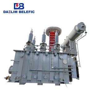
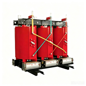
Selecting the optimal compact transformer technology depends on installation environment, fire safety protocols, and operational maintenance capacities. Below is a comparative technical analysis of the three core compact transformer designs:
Technical Parameter
Oil-Immersed Compact Transformer
Cast Resin Dry Type (SCB)
Vacuum Pressure Impregnated (VPI)
Power Rating Range
50 kVA – 10,000 kVA
100 kVA – 5,000 kVA
100 kVA – 3,150 kVA
Insulation Class
Class A (105°C) / Class A+ Ester
Class F (155°C) / Class H (180°C)
Class H (180°C) / Class C (220°C)
Cooling Medium
Mineral Oil / Synthetic Ester Fluid
Natural Air (AN) / Forced Air (AF)
Fire Hazard Level
Requires fire barriers/containment pit
Self-extinguishing (F1 rating)
Non-flammable, moisture resistant
Enclosure Protection
Hermetically Sealed (IP54/IP65)
IP20 to IP44 Enclosures
IP23 to IP54 Ventilated Enclosures
Thermal Shock Resistance
Excellent
Moderate (Risk of micro-cracking)
Superior (Flexible resin matrix)
Maintenance Profile
Oil testing, DGA analysis, Drier checks
Minimal (Dusting, visual checks)
Minimal (Moisture-tolerant)
3. Core Technological Advances in Compact Transformer Design
A. Amorphous Alloy vs. Cold-Rolled Grain-Oriented (CRGO) Silicon Steel
The core material choice directly governs no-load (hysteresis and eddy current) losses. Premium OEM/ODM manufacturers offer high-grade CRGO (M0H, M1H grades) as well as Amorphous Alloy core structures:
CRGO Cores: Precision step-lap 45-degree mitred joint construction minimizes flux distortion at the joints, reducing no-load losses by up to 15% and lowering acoustic noise levels to comply with residential urban standards (NEMA/IEEE ST-20).
Amorphous Alloy Cores: Possessing a non-crystalline atomic structure, amorphous cores reduce no-load standby losses by 70% to 80% compared to traditional silicon steel, fulfilling strict international energy efficiency metrics (such as US DOE 2026 guidelines and EU EcoDesign Directive Tier 2).
B. Thermal Management & Forced-Air Augmentation
Compact substations enclose transformers within tight steel or GRC (Glass-fiber Reinforced Concrete) housings. Thermal accumulation is the primary driver of insulation breakdown. Advanced OEM factories utilize computational fluid dynamics (CFD) to design optimized airflow channels inside compact substations:
Integrating smart temperature controllers with RS485 Modbus communications allows dynamic switching of forced-air (AF) cooling fans. This temporarily boosts transformer continuous kVA capacity by 33% to 50% during peak demand periods without exceeding allowable winding temperature rises (65°C for oil-filled, 90°C/115°C for dry-type units).
C. Harmonic Mitigation in Converter & Rectifier Duty Compact Units
With the surge in industrial VFD drives, solar PV central inverters, and EV charging hubs, transformers are increasingly subjected to non-linear harmonic loads (THD). Harmonics induce severe eddy current losses in windings and stray losses in structural clamps. OEM/ODM custom engineering incorporates:
Electrostatic shielding between primary and secondary windings to divert high-frequency common-mode noise to ground.
Transposed rectangular copper conductors to reduce skin and proximity effect losses.
Derating designs using K-factor calculations (K-4, K-13, K-20 rated) to handle harmonic heating safely.
4. Global Sourcing Trends & Future Market Outlook (2025–2035)
Environmental regulations and urban fire codes are pushing utility buyers away from traditional mineral oil. Synthetic and natural ester fluids feature fire points exceeding 300°C (K-class fluids), enabling liquid-filled compact transformers to be safely deployed indoors, on offshore rigs, and within underground substations where dry-type transformers were previously mandatory.
Trend 2: Integration of Smart IoT & Online Asset Health Monitoring
Modern compact substations are no longer isolated passive assets. International buyers now mandate integrated IoT sensors that transmit operational telemetry to SCADA or cloud platforms. Key monitored variables include:
Real-time Dissolved Gas Analysis (DGA) for early hydrogen and acetylene fault detection.
Fiber-optic direct winding hotspot temperature sensing.
Vibration and acoustic spectral analysis for detecting core loosening or internal mechanical displacement following downstream short-circuit events.
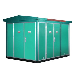
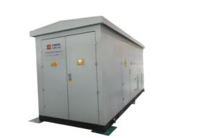
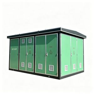
To reduce expensive site civil works and installation timelines, procurement orders are shifting heavily toward fully unitized compact substations (e.g., YBW series). These units integrate High Voltage Switchgear (SF6 Ring Main Unit or Vacuum Circuit Breaker), the step-down Compact Transformer, and Low Voltage Distribution Boards inside a single factory-tested, IP54-rated weather-proof enclosure.
Q1: What is the main distinction between European-style and American-style Compact Substations?
European-Style Compact Substations: Feature independent structural compartments for the HV switchgear, transformer, and LV distribution panel. This modular separation offers high operational safety, easier maintenance access, and accommodates larger transformer capacities (up to 2500 kVA or higher).
American-Style (Pad-Mounted) Substations: The transformer tank and switchgear are integrated into a single unified housing, where the HV load-break switches and fuses are immersed directly inside the transformer oil tank. This yields an extremely compact, low-profile footprint ideal for residential neighborhoods and space-constrained commercial sites, typically up to 1500 kVA.
Q2: How does factory type testing (CPRI / ERDA) protect international procurement buyers?
Type tests are destructive and non-destructive laboratory evaluations conducted on representative production units to verify fundamental engineering design. Independent certifications from accredited bodies like CPRI (Central Power Research Institute) or ERDA (Electrical Research and Development Association) validate:
1. Short-Circuit Dynamic Withstand Strength: Proves the windings will not collapse or deform under catastrophic external grid faults.
2. Lightning Impulse Voltage Test: Verifies dielectric insulation integrity against severe transient overvoltage surges.
3. Temperature Rise Test: Ensures continuous full-load thermal stability without degrading insulation paper or oil properties.
Q3: What engineering considerations are required for transformers operating in high ambient temperature environments (>50°C)?
In tropical or desert regions (e.g., Middle East, Mining sites), high ambient temperatures reduce natural cooling efficiency. OEM customization requires:
- Designing for a lower top-oil and winding temperature rise limit (e.g., 50°C rise instead of standard 65°C).
- Increasing core cross-sectional area and using larger copper wire gauges to lower current density ($A/mm^2$) and reduce $I^2R$ copper losses.
- Expanding cooling radiator surface areas and specifying UV-resistant, high-durability C5-M marine grade external paint finishes to prevent corrosion.
Q4: What is the typical lead time for custom OEM/ODM compact transformer prototyping and mass production?
Standard technical approval and manufacturing lead times follow a structured milestone timeline:
- Phase 1: Engineering Approval (1–2 Weeks): SLD confirmation, enclosure dimensional modeling, accessory selection, and client drawing sign-off.
- Phase 2: Core, Coil & Enclosure Fabrication (3–5 Weeks): Precision CNC steel punching, core slitting, copper disc/layer winding, vacuum drying, and tank welding.
- Phase 3: Assembly & Routine Testing (1–2 Weeks): Vacuum oil filling/dry-type resin curing, turns ratio, winding resistance, insulation power factor, and routine high-voltage withstand testing.
- Total Estimated Production Time: 6 to 8 weeks for custom industrial units.
Partner with a Certified OEM/ODM Compact Transformer Factory
Need custom technical drawings, budget estimation, or CPRI/ERDA type test reports for your upcoming tender or project? Our senior electrical engineering team is ready to assist.