Featured Wind & Industrial Power Transformers
Factory-direct OEM/ODM transformer solutions designed to withstand harmonic distortion, high mechanical vibration, and aggressive environmental exposure.
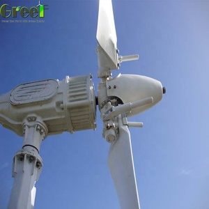
Aluminium Body Small Wind Turbine for Farm
- Structure: Lightweight Corrosion-Resistant Enclosure
- Application: Microgrid & Agricultural Off-Grid Systems
- Efficiency: Optimized Low Cut-in Wind Speed Output
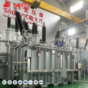
Yawei Manufacturer Price 10 MVA 15MVA 20MVA 67KV 69KV 33KV Power Transformer Copper Winding 60hz Dyn11
- Capacity: 10 MVA to 20 MVA Step-Up Utility Power
- Primary Voltage: 33kV, 67kV, 69kV (High Voltage Inter-Array)
- Winding: 100% Electrolytic Copper Vector Dyn11
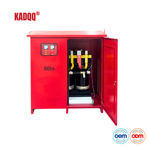
Wind Turbine Generator Isolation Transformer 800KVA Three Phase IP65 Protection CE Certified for Renewable Energy Systems
- Rating: 800 kVA Heavy Harmonic Filtering
- Enclosure: IP65 Weatherproof Heavy-Duty Housing
- Standard: CE Certified & Low-Loss Eco-Design
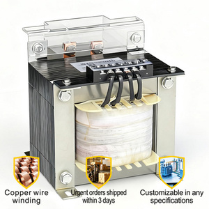
5KVA 10kVA Single Phase Control Transformer 110/220V To 36/48V For Packaging Machinery Pure Copper Winding CE ISO
- Type: Auxiliary Control Transformer (5kVA / 10kVA)
- Voltage Step-Down: 110/220V to 36/48V Safety Output
- Certification: ISO 9001 & CE Quality Assured
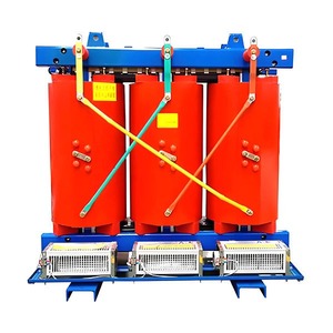
Customizable Fire Prevention Buildings Use Isolation Copper Winding Three Phase 33KV 35KV 38.5KV Wind Turbine Dry Transformer
- Tech: Fire-Safe VPI / Cast Resin Isolation Insulation
- Voltage Class: 33kV, 35kV, 38.5kV Nacelle-Ready
- Safety: Self-Extinguishing F1 / C2 / E2 Fire Class
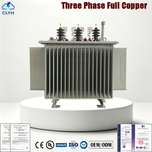
Distribution Transformer 100kVA 10/0.4kV Three Phase Oil Immersed Copper Winding IEC CE Certified 50Hz For Utility Grid
- Rating: 100 kVA 10/0.4kV Utility Substation Step-Down
- Cooling: Hermetically Sealed Oil Immersed (ONAN)
- Compliance: IEC 60076 & Level 1 Loss Requirements
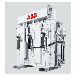
ABB (Hitachi Energy) Offshore Wind Turbine Transformer 5-25MVA 66-72.5KV IEC Genuine Standard Replacement
- Capacity Range: 5 MVA to 25 MVA High Density Step-Up
- Voltage Horizon: 66kV to 72.5kV Inter-Array Grids
- Environment: Offshore Salt-Spray & Nacelle Anti-Vibration
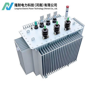
S11 3 Phase Oil Immersed Distribution Transformer 10kV 0.4kV 100% Copper Winding Power Transformer
- Model: Low-Loss S11 High Energy Efficiency Series
- Core Design: Stacked Cold-Rolled Grain-Oriented Silicon Steel
- Winding: 100% Pure Oxygen-Free Electrolytic Copper
OEM/ODM Wind Turbine Step-Up Transformer Engineering Framework
Addressing the operational challenges of modern wind farms through heavy-duty insulation, harmonic containment, and robust thermal architecture.
Thermal & Harmonic Stress Resilience
Modern wind turbine generators utilize high-frequency PWM IGBT power converters that inject severe high-order harmonics ($K$-factor ratings up to K-13 or higher) into the step-up transformer LV windings.
Our custom OEM/ODM wind transformers incorporate electrostatic shielding between HV and LV windings alongside transposed rectangular copper conductors to eliminate localized hot-spots and stray eddy losses under fluctuating wind loads.
Vibration-Safe Structural Design
Turbine nacelle installations expose transformers to relentless structural oscillations and dynamic 3D mechanical vibration (0.5G to 3.0G continuous acceleration forces).
We employ vacuum pressure impregnation (VPI) with Class H silicone resins, heavy-duty core clamping frames, and anti-vibration elastomeric damper mounts that ensure structural natural resonance frequencies remain far beyond turbine operating bands.
Offshore Marine Corrosion Shield (C5-M)
Offshore wind arrays require transformer enclosures capable of enduring high humidity, salt spray, and aggressive marine environments over a 25-to-30-year operational lifespan.
Our offshore oil-immersed and dry-type enclosures feature ISO 12944 C5-M compliant multi-layer epoxy powder coating systems or 316L stainless steel tanks engineered for zero-maintenance performance in marine substations.
VPI Dry-Type vs. Cast Resin vs. Ester-Filled Transformers
Comparing key structural and electrical parameters for optimal tower-base, nacelle, or substation deployment.
| Transformer Technology | Dielectric / Insulation System | Max Rated Voltage | Fire Safety Rating | Vibration Endurance | Ideal Installation Site |
|---|---|---|---|---|---|
| Vacuum Pressure Impregnated (VPI) | Class H / C DuPont Nomex® Resin | Up to 38.5 kV | Self-Extinguishing (F1) | Extreme (>3.0G Acceleration) | Nacelle Interior & Tower Base |
| Cast Resin Dry-Type (CRT) | Class F Epoxy Resin Encasement | Up to 36 kV | Non-Flammable (F1) | Moderate to High (1.5G) | Tower Base & Indoor Substation |
| Synthetic Ester Oil-Immersed | Biodegradable Synthetic Ester Fluid | Up to 72.5 kV | High Flash Point (>300°C) | High (Reinforced Core Frame) | Offshore Nacelle & Platform Substation |
| Mineral Oil-Immersed (S11/S13) | High-Refinement Naphthenic Mineral Oil | Up to 69 kV | Standard Flash Point (145°C) | Standard Grid Duty | Onshore Substation & Ground Pad |
Future Procurement Trends in Wind Transformer Sourcing
Key market shifts and technological advancements driving global utility and EPC procurement strategies through 2030.
1. Transition to 66kV / 72.5kV Inter-Array Networks
Global wind farm developers are rapidly shifting from traditional 33kV collector systems to 66kV and 72.5kV inter-array voltage levels. Elevating inter-array voltage reduces levelized cable losses by up to 50% and minimizes offshore cabling weight.
Our OEM/ODM manufacturing facility produces compact 66kV step-up transformers with low partial discharge values (<5 pC) specifically engineered to fit within tight turbine tower dimensions.
2. Adoption of Eco-Friendly Synthetic Ester Fluids
Environmental regulations and risk management policies are pushing utilities away from mineral oils toward rapidly biodegradable synthetic and natural ester dielectrics.
Ester fluids feature a fire point exceeding 300°C (Class K fluid rating), eliminating the requirement for complex fire-suppression equipment in nacelles while ensuring zero toxic residual contamination in the event of marine offshore spills.
3. Integrated Smart IoT & Condition Monitoring
Next-generation wind asset management relies on continuous digital diagnostics. Modern OEM specifications require transformers equipped with integrated fiber-optic temperature sensors, real-time Dissolved Gas Analysis (DGA) monitors, and online partial discharge measurement nodes.
Our ODM engineering team embeds multi-protocol IoT sensors compatible with IEC 61850 substation automation standards for predictive maintenance.
Why Partner With Our OEM/ODM Transformer Factory
Over three decades of precision electrical manufacturing backed by international type tests, rigorous quality control, and worldwide export experience.
CPRI & ERDA Type-Tested Guarantee
Every transformer design line undergoes comprehensive third-party type testing at premier independent laboratories, including the Central Power Research Institute (CPRI) and Electrical Research and Development Association (ERDA).
Testing protocols validate short-circuit withstand performance, lightning impulse withstand capabilities, temperature rise limits, acoustic noise levels, and partial discharge thresholds per IEC 60076 and IS 2026 standards.
Fully Customizable OEM/ODM Engineering
We provide end-to-end custom engineering tailoring voltage ratios, vector groups (Dyn11, Dyn5, YNd11), dual LV winding arrangements, special footings, dimensional constraints, and specialized bushing positioning (top, side, or bottom cable boxes).
Our engineering team works directly with turbine OEMs, EPC contractors, and utility operators to satisfy exact project grid-code requirements.
Proven International Export Track Record
With over 40% of total output exported to more than 40 countries across Europe, Africa, the Middle East, and Southeast Asia, our factory understands global export logistics, marine seaworthy packaging, and international standards compliance.
All units ship with comprehensive factory inspection test reports (FAT), material traceability documentation, and full warranty coverage.
Frequently Asked Questions by B2B Buyers & Engineers
Expert insights on transformer selection, customization options, operational limits, and quality compliance.
Q1: Why do wind turbine transformers experience higher failure rates than standard distribution transformers?
Wind turbine step-up transformers (GSU) operate under severe conditions: intense thermal cycling from fluctuating wind speeds, frequent dielectric switching surges from circuit breakers, high harmonic loading ($K$-factor distortion) from grid-tied inverters, and heavy structural vibration inside the tower or nacelle. Standard distribution units lack the mechanical reinforcement, electrostatic shielding, and thermal margin required for continuous reliability under these conditions.
Q2: What are the advantages of Vacuum Pressure Impregnation (VPI) over Cast Resin in wind applications?
VPI dry-type transformers utilize Class H insulation (such as DuPont Nomex®) impregnated with silicone resin under deep vacuum and high pressure. This provides dynamic elasticity, enabling the winding structure to absorb severe vibration (up to 3G acceleration) without micro-cracking—a common failure mode in rigid cast resin units exposed to high physical motion inside wind turbine nacelles.
Q3: How do your transformers handle inverter harmonics and high K-factor ratings?
Our OEM wind transformers are engineered with specialized low-loss conductor geometries, stray-flux shielding, and transposed copper windings. We incorporate grounded electrostatic copper shields between the primary and secondary windings to bypass high-frequency switching transients, preventing capacitive coupling of PWM inverter noise onto the high-voltage collector grid.
Q4: What customized OEM/ODM design options can your factory accommodate?
We provide complete customization, including dimensional footprint matching for tight tower bases, dual-LV winding configurations (to connect dual inverters to a single step-up transformer), integrated On-Load Tap Changers (OLTC) or Off-Circuit Tap Changers (OCTC), specialized neutral grounding options, ester-fluid filling, and custom corrosion-resistant paint systems (C5-M marine rating).
Q5: What routine and factory acceptance tests (FAT) are conducted on wind transformers?
Each transformer undergoes strict Factory Acceptance Testing per IEC 60076 and IS 2026, including: Winding Resistance Measurement, Voltage Ratio and Vector Group Verification, Short-Circuit Impedance and Load Loss Testing, No-Load Loss and Current Testing, Separate-Source AC Dielectric Withstand, Induced Overvoltage Withstand, and Partial Discharge Discharge (<5 pC for dry-type units).
Q6: How do ester fluids improve fire safety and environmental rating?
Synthetic and natural ester liquids have a fire flash point exceeding 300°C (Class K fluid rating), making them virtually unignitable under normal transformer operating conditions. Additionally, synthetic esters are non-toxic and achieve 100% biodegradation within 28 days (OECD 301), satisfying strict environmental protection directives for offshore and eco-sensitive wind developments.
Q7: How do your transformers comply with Low-Voltage Ride-Through (LVRT) grid requirements?
During grid fault events, wind transformers experience massive electromagnetic mechanical forces due to sudden short-circuit current surges. Our wind turbine transformers feature reinforced core clamping assemblies and high-mechanical-strength insulated conductors designed and verified by CPRI/ERDA short-circuit withstand calculations to endure maximum LVRT fault stress without mechanical deformation.
Q8: What is the typical lead time for custom OEM wind transformer orders?
Standard customized prototypes and initial OEM engineering drawings are delivered within 1 to 2 weeks. Production lead times typically range from 6 to 10 weeks depending on transformer voltage class, core material availability, and specific client factory testing requirements. Accelerated manufacturing protocols are available for urgent utility utility grid repowering projects.
Request a Custom OEM/ODM Engineering Proposal
Connect directly with our senior transformer application engineers to discuss your project specifications, obtain budget estimates, or request comprehensive type-test reports.